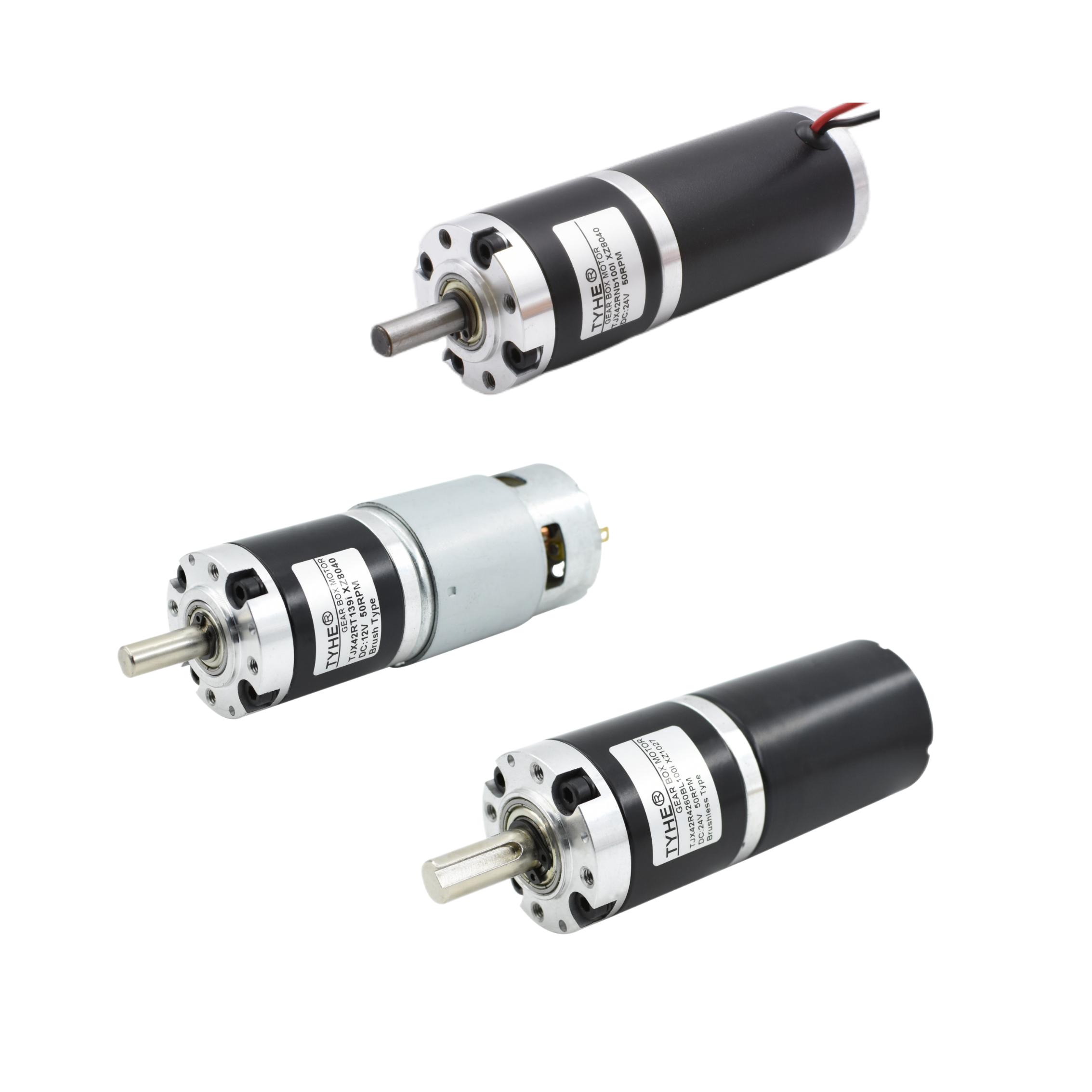
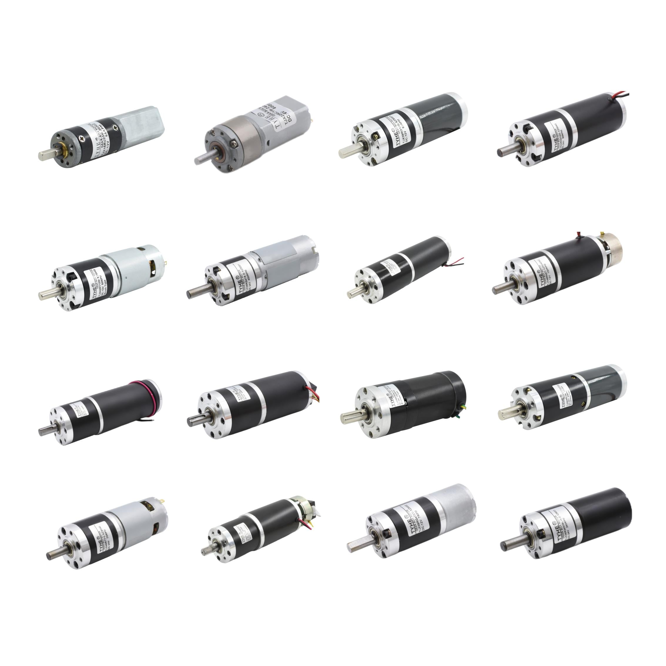
gear reduction dc motor
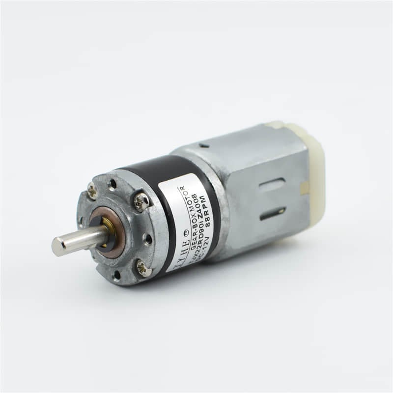
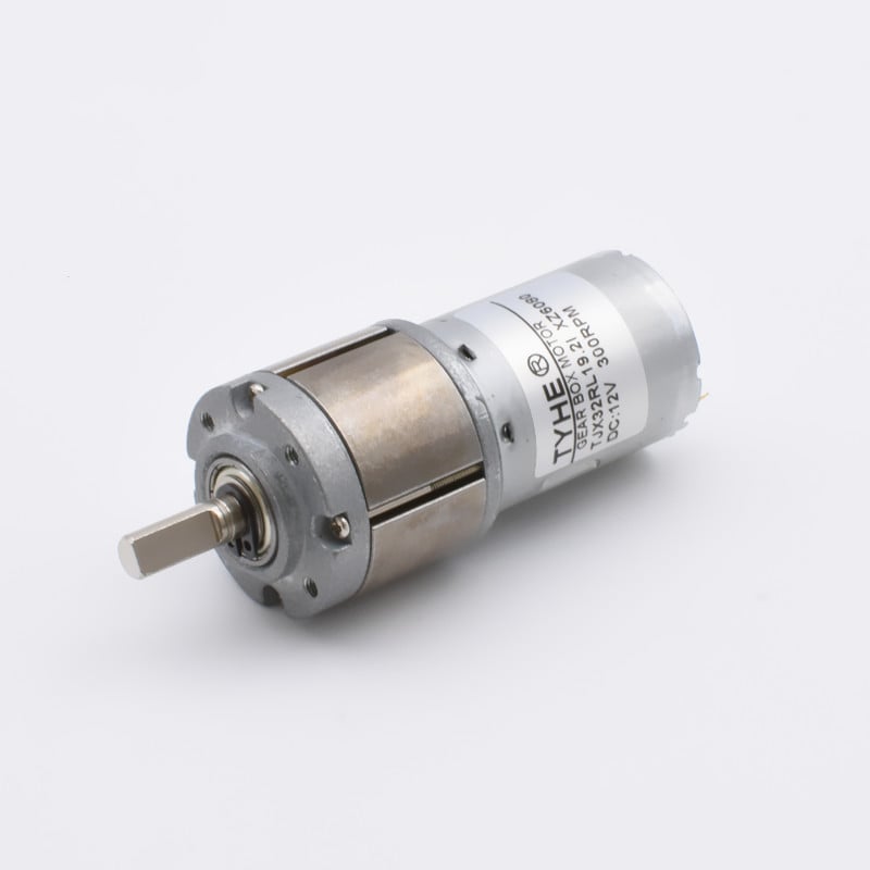
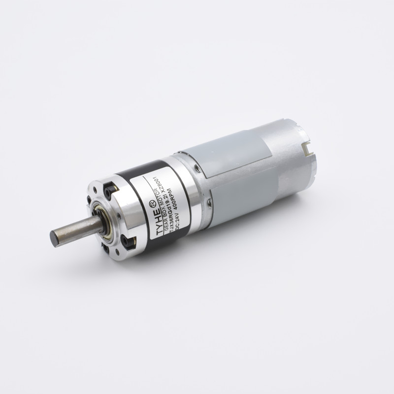
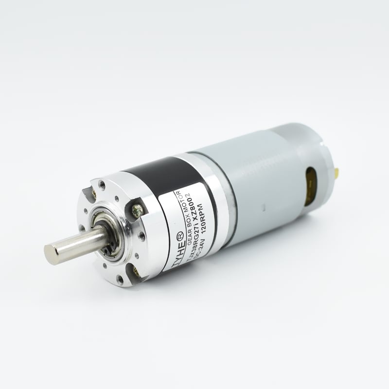
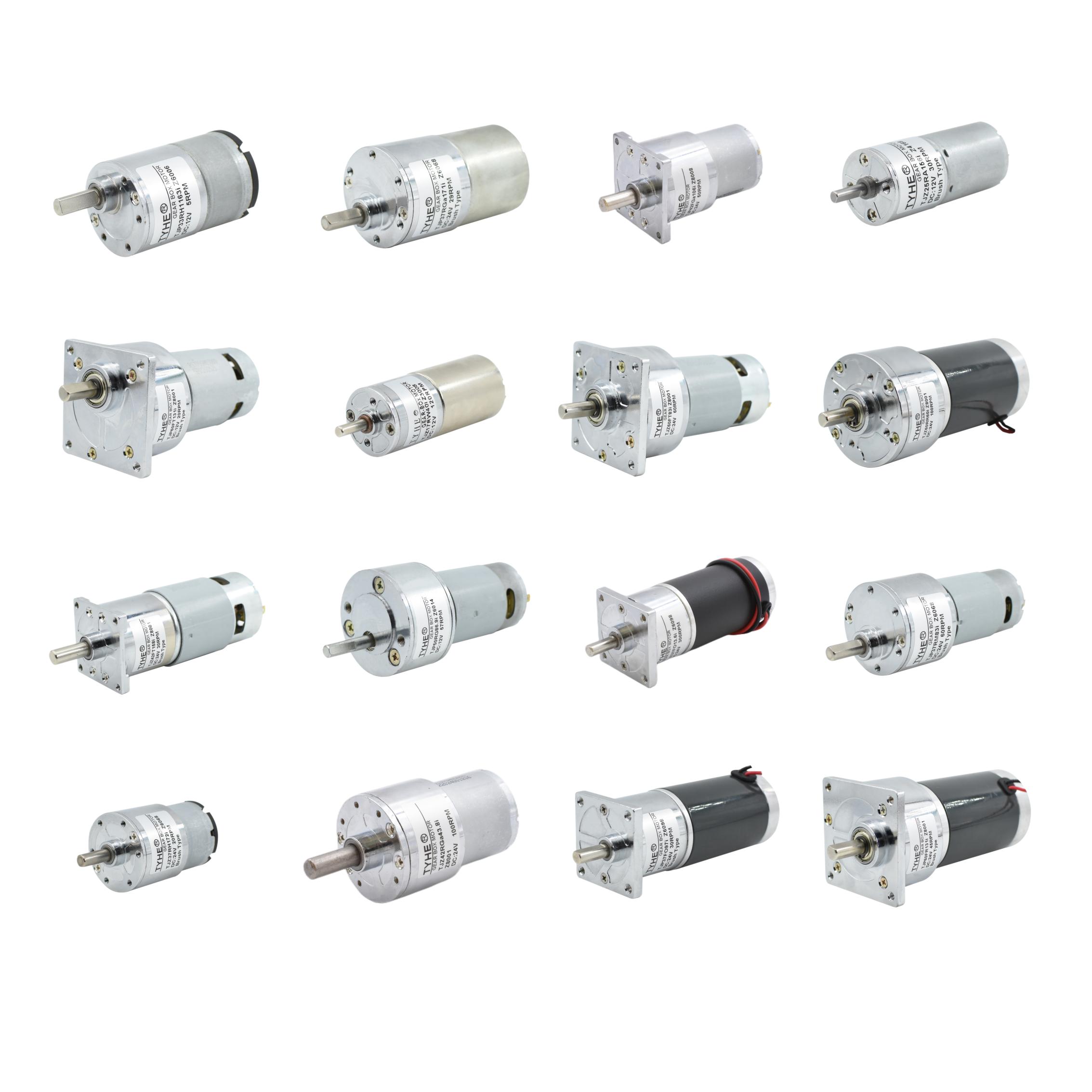
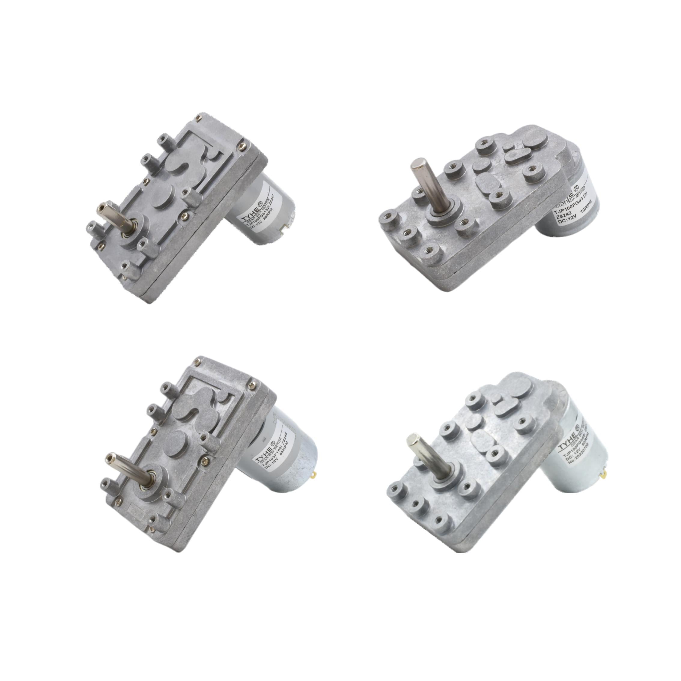
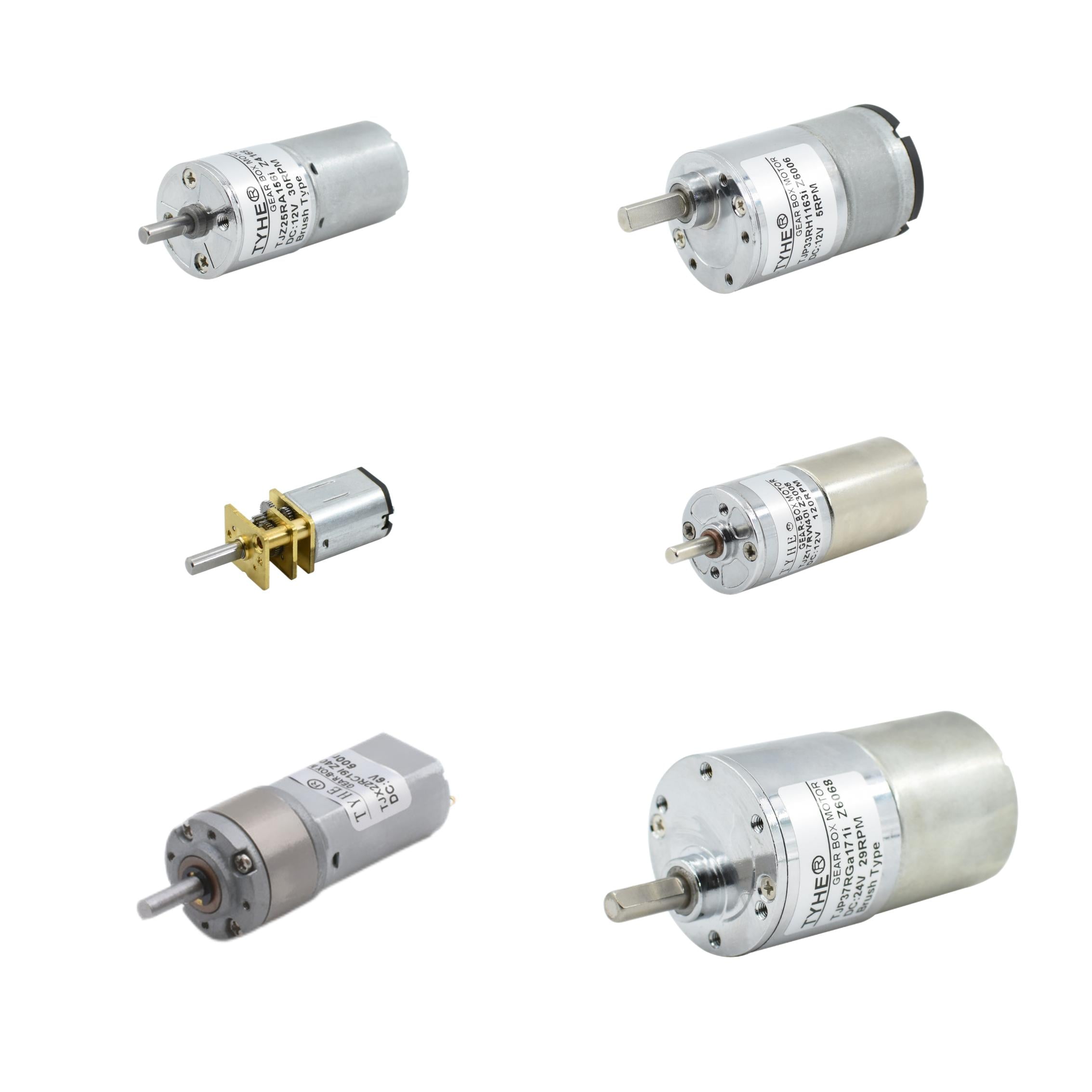
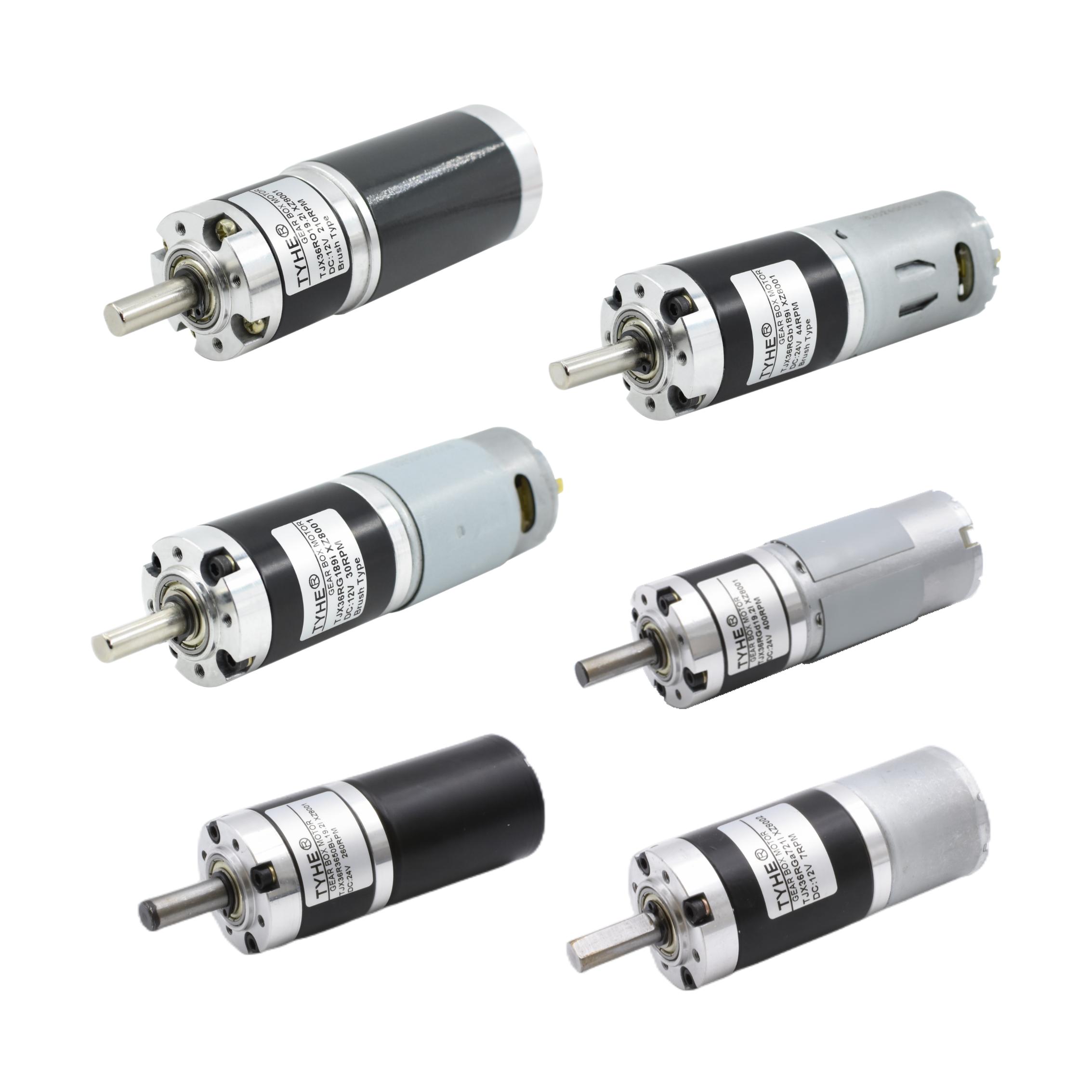
A gear reduction dc motor combines a direct current motor with a gearbox to deliver controlled speed and higher turning force. The motor creates rotational energy, while the gear train reduces output speed and increases torque for practical machine movement. This design helps a gear reduction dc motor handle loads that a standard motor may struggle to start or move. A gear reduction dc motor suits systems that need steady, repeatable motion rather than high free-running speed. Common configurations include spur, planetary, and worm gear systems. Each option offers different levels of efficiency, holding ability, noise control, and compactness. A gear reduction dc motor can use brushed or brushless motor technology, depending on the required service life, control method, and maintenance plan. Voltage options often include 6 V, 12 V, 24 V, and other custom ratings. A gear reduction dc motor may also include an encoder, limit switch, brake, or feedback sensor for accurate positioning. Speed control works through voltage adjustment, pulse-width modulation, or a dedicated controller. A gear reduction dc motor provides forward and reverse rotation when paired with a suitable driver or polarity circuit. Its metal or reinforced plastic housing protects internal parts and supports different mounting arrangements. Buyers can specify shaft size, gear ratio, rated torque, no-load speed, current draw, and duty cycle. The gear reduction dc motor appears in conveyors, automatic doors, medical equipment, robots, pumps, valves, lifting systems, toys, and office machines. Selecting the correct gear ratio allows a gear reduction dc motor to balance speed, force, size, and energy use for the intended task.

 EN