
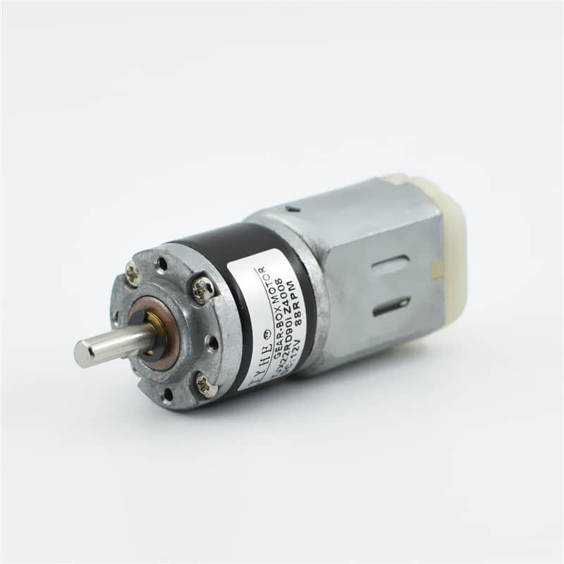
The evolution of modern technology has created an unprecedented demand for compact, efficient power solutions across diverse applications. In today's miniaturized world, engineers and designers constantly seek reliable components that deliver maximum performance within minimal space constraints. A micro dc motor represents the perfect intersection of power, precision, and portability, making it an indispensable component in countless electronic devices, medical equipment, and automation systems.
Understanding the specifications of these miniature powerhouses requires careful examination of multiple parameters that directly impact performance, longevity, and application suitability. From voltage requirements to torque characteristics, each specification plays a crucial role in determining whether a particular motor meets the demanding requirements of your specific application. This comprehensive analysis will explore the fundamental aspects that define micro dc motor performance and guide you through the selection process.
Essential Performance Characteristics
Voltage and Current Requirements
The voltage rating of a micro dc motor fundamentally determines its operational parameters and compatibility with existing power systems. Most micro dc motor units operate within voltage ranges from 1.5V to 24V, with common configurations including 3V, 6V, 9V, and 12V variants. The specified voltage directly correlates with the motor's speed, torque output, and power consumption characteristics, making this specification critical for application matching.
Current consumption patterns vary significantly based on load conditions and operational demands. No-load current typically ranges from 10mA to 200mA, while stall current can reach several amperes depending on the motor size and design. Understanding these current characteristics ensures proper power supply sizing and thermal management considerations in your application design.
The relationship between voltage and current creates the foundation for power calculations and efficiency assessments. Higher voltage operations generally enable increased speed capabilities, while current consumption directly impacts battery life in portable applications. Designers must carefully balance these parameters to achieve optimal performance within their specific constraints.
Speed and Torque Specifications
Speed ratings for micro dc motor applications typically range from 1,000 to 30,000 RPM, depending on the intended use case and internal gear ratios. No-load speed represents the maximum rotational velocity under ideal conditions, while loaded speed provides more realistic performance expectations. The speed-torque curve characterizes how motor performance changes under varying load conditions.
Torque specifications include starting torque, running torque, and stall torque measurements. Starting torque indicates the motor's ability to overcome initial resistance and begin rotation, while running torque represents continuous operational capability. Stall torque defines the maximum load the motor can handle before stopping, providing crucial information for application safety margins.
The inverse relationship between speed and torque means that applications requiring high rotational speeds typically sacrifice torque capability, while high-torque applications operate at lower speeds. Understanding this fundamental trade-off enables engineers to select motors that provide optimal performance for their specific requirements.
Physical and Mechanical Specifications
Dimensional Constraints and Form Factors
Physical dimensions represent critical selection criteria for micro dc motor applications where space constraints dominate design decisions. Standard diameter measurements range from 6mm to 25mm, with lengths varying from 10mm to 50mm depending on power requirements and internal construction. These compact dimensions enable integration into devices where traditional motors would be impractical.
Mounting configurations include various shaft orientations, housing designs, and connection methods that accommodate different installation requirements. Some applications require specific shaft lengths, diameters, or coupling mechanisms that must align with existing mechanical systems. The motor housing material and finish also impact durability and environmental resistance.
Weight considerations become particularly important in battery-powered devices, aerospace applications, and handheld equipment. A typical micro dc motor weighs between 5 grams and 100 grams, making weight optimization possible without sacrificing performance capabilities. This weight efficiency enables new possibilities in portable device design and robotic applications.
Environmental and Durability Factors
Operating temperature ranges define the environmental conditions under which the micro dc motor maintains reliable performance. Standard operating temperatures typically span from -20°C to +85°C, though specialized versions can handle more extreme conditions. Temperature coefficients affect performance parameters, with higher temperatures generally reducing efficiency and lifespan.
Humidity resistance and ingress protection ratings determine suitability for outdoor or industrial applications. Many micro dc motor designs incorporate sealed housings or special coatings to prevent moisture infiltration and contamination. These protective measures ensure consistent performance across diverse environmental conditions.
Vibration resistance and shock tolerance specifications become crucial in mobile applications or harsh operating environments. The internal construction, bearing quality, and housing design all contribute to the motor's ability to maintain performance despite mechanical stresses. Understanding these limitations prevents premature failure and ensures reliable operation.
Electrical Characteristics and Control Parameters
Efficiency and Power Consumption
Efficiency ratings directly impact battery life, heat generation, and overall system performance in micro dc motor applications. Typical efficiency values range from 40% to 85%, depending on the motor design, load conditions, and operating speed. Higher efficiency motors reduce power consumption and extend operational time in battery-powered devices.
Power consumption calculations must account for both mechanical load and electrical losses within the motor windings and bearings. The relationship between input power and output power determines the thermal management requirements and helps predict operational costs. Efficiency curves show how performance varies across different operating points.
Heat dissipation characteristics affect both performance stability and component longevity. Micro dc motor designs must balance power density with thermal management to prevent overheating during continuous operation. Understanding thermal characteristics enables proper heat sinking and ventilation design in the final application.
Control Interface and Signal Requirements
Speed control methods vary from simple voltage regulation to sophisticated pulse-width modulation techniques. Many micro dc motor applications benefit from electronic speed controllers that provide precise velocity control and protection features. The motor's electrical time constant affects response speed and control system design requirements.
Direction control typically requires H-bridge circuits or similar switching arrangements to reverse current flow through the motor windings. The control interface complexity depends on application requirements, with some systems requiring only basic on/off control while others demand precise speed and position feedback.
Feedback systems may incorporate encoders, Hall sensors, or back-EMF sensing to provide position or speed information. These feedback mechanisms enable closed-loop control systems that maintain precise operational parameters despite load variations or environmental changes. The integration of sensors adds complexity but significantly improves performance capabilities.
Application-Specific Considerations
Load Matching and Performance Optimization
Proper load matching ensures that the micro dc motor operates within its optimal performance range while avoiding premature wear or failure. The load characteristics, including inertia, friction, and varying torque requirements, must align with the motor's capabilities. Mismatched loads can result in poor efficiency, excessive heat generation, or inadequate performance.
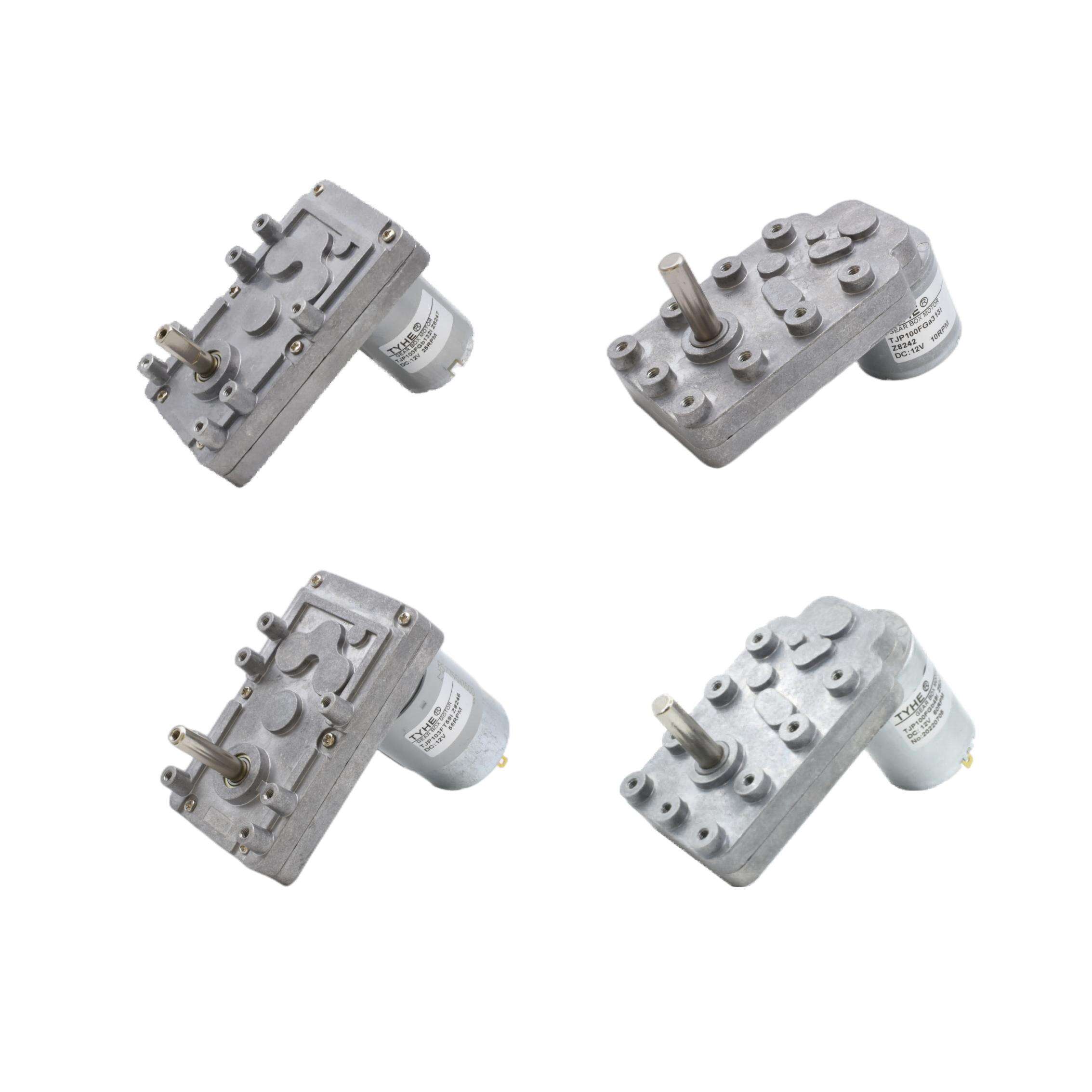
Gear reduction systems often accompany micro dc motor installations to modify the speed-torque relationship for specific applications. These mechanical interfaces multiply torque while reducing speed, enabling motors to drive higher loads than their direct specifications would suggest. The gear ratio selection significantly impacts overall system performance and efficiency.
Dynamic response characteristics determine how quickly the motor can accelerate, decelerate, or change direction in response to control inputs. Applications requiring rapid response times need motors with low inertia and high torque-to-inertia ratios. Understanding these dynamic properties ensures suitable motor selection for time-critical applications.
Reliability and Maintenance Requirements
Service life expectations vary dramatically based on operating conditions, load factors, and duty cycles. A well-specified micro dc motor can operate for thousands of hours under proper conditions, while harsh environments or overloading can significantly reduce lifespan. Manufacturers typically provide MTBF (Mean Time Between Failures) ratings under specified conditions.
Brush life represents a primary wear mechanism in traditional brushed micro dc motor designs. The brush material, commutator quality, and operating conditions all affect brush longevity. Brushless alternatives eliminate this wear mechanism but require more complex control electronics and typically cost more initially.
Preventive maintenance requirements range from minimal for sealed units to periodic lubrication or brush replacement for serviceable designs. Understanding maintenance needs helps determine total cost of ownership and operational complexity. Some applications cannot tolerate maintenance requirements, making motor selection crucial for long-term reliability.
Selection Guidelines and Best Practices
Specification Prioritization
Successful micro dc motor selection requires prioritizing specifications based on application criticality and performance requirements. Primary considerations typically include physical size constraints, power requirements, and environmental conditions. Secondary factors encompass cost, availability, and specific performance characteristics that enhance but don't define basic functionality.
Creating a specification matrix helps evaluate different motor options against weighted criteria. This systematic approach prevents overlooking important characteristics while focusing attention on the most critical parameters. The matrix should include minimum acceptable values, preferred ranges, and deal-breaker limitations for each specification.
Performance margins provide safety factors that account for manufacturing tolerances, aging effects, and unexpected operating conditions. Selecting motors with capabilities exceeding minimum requirements ensures reliable operation throughout the product lifecycle. However, over-specification can unnecessarily increase costs and complexity.
Testing and Validation Procedures
Prototype testing validates theoretical specifications against real-world performance requirements. Test protocols should encompass normal operating conditions, environmental extremes, and failure mode analysis. Comprehensive testing reveals potential issues before full-scale production and ensures specification compliance.
Accelerated life testing predicts long-term reliability by subjecting micro dc motor samples to elevated stress conditions. These tests compress months or years of normal operation into shorter timeframes, revealing wear patterns and failure modes. The results help establish maintenance schedules and warranty terms.
Quality assurance procedures ensure consistent performance across production quantities. Incoming inspection, statistical sampling, and burn-in testing help identify defective units before installation. Establishing quality standards prevents field failures and maintains customer satisfaction throughout the product lifecycle.
FAQ
What voltage range is suitable for most micro dc motor applications
Most micro dc motor applications operate successfully within 3V to 12V ranges, with 6V and 9V being particularly common in consumer electronics and small automation systems. The specific voltage requirement depends on your speed and torque needs, with higher voltages generally providing increased performance capabilities. Battery-powered applications often use 3V or 6V motors to match standard battery configurations, while mains-powered devices may utilize 12V or 24V options for enhanced performance.
How do I calculate the required torque for my application
Torque calculations require analyzing all resistive forces in your system, including friction, inertia, and external loads. Start by identifying the load mass, operating radius, and acceleration requirements, then apply the formula: Torque = Force × Radius + Inertial torque. Add a safety margin of 20-50% to account for efficiency losses and unexpected loads. Consider peak torque requirements during startup or direction changes, as these often exceed steady-state needs.
What factors affect micro dc motor lifespan and reliability
Several key factors influence micro dc motor longevity, including operating temperature, load conditions, duty cycle, and environmental exposure. Continuous high-load operation reduces lifespan more than intermittent use, while elevated temperatures accelerate wear mechanisms. Proper load matching, adequate cooling, and protection from moisture and contaminants significantly extend operational life. Brushed motors have additional wear considerations related to brush and commutator condition.
Can I control micro dc motor speed without complex electronics
Simple speed control is achievable using variable resistors or basic PWM circuits, though more sophisticated control provides better performance and efficiency. Voltage regulation through resistive methods works for basic applications but wastes power as heat. PWM control offers superior efficiency and precision, requiring only basic electronic components. For applications demanding precise speed maintenance under varying loads, feedback control systems become necessary but add complexity and cost.
