
 EN
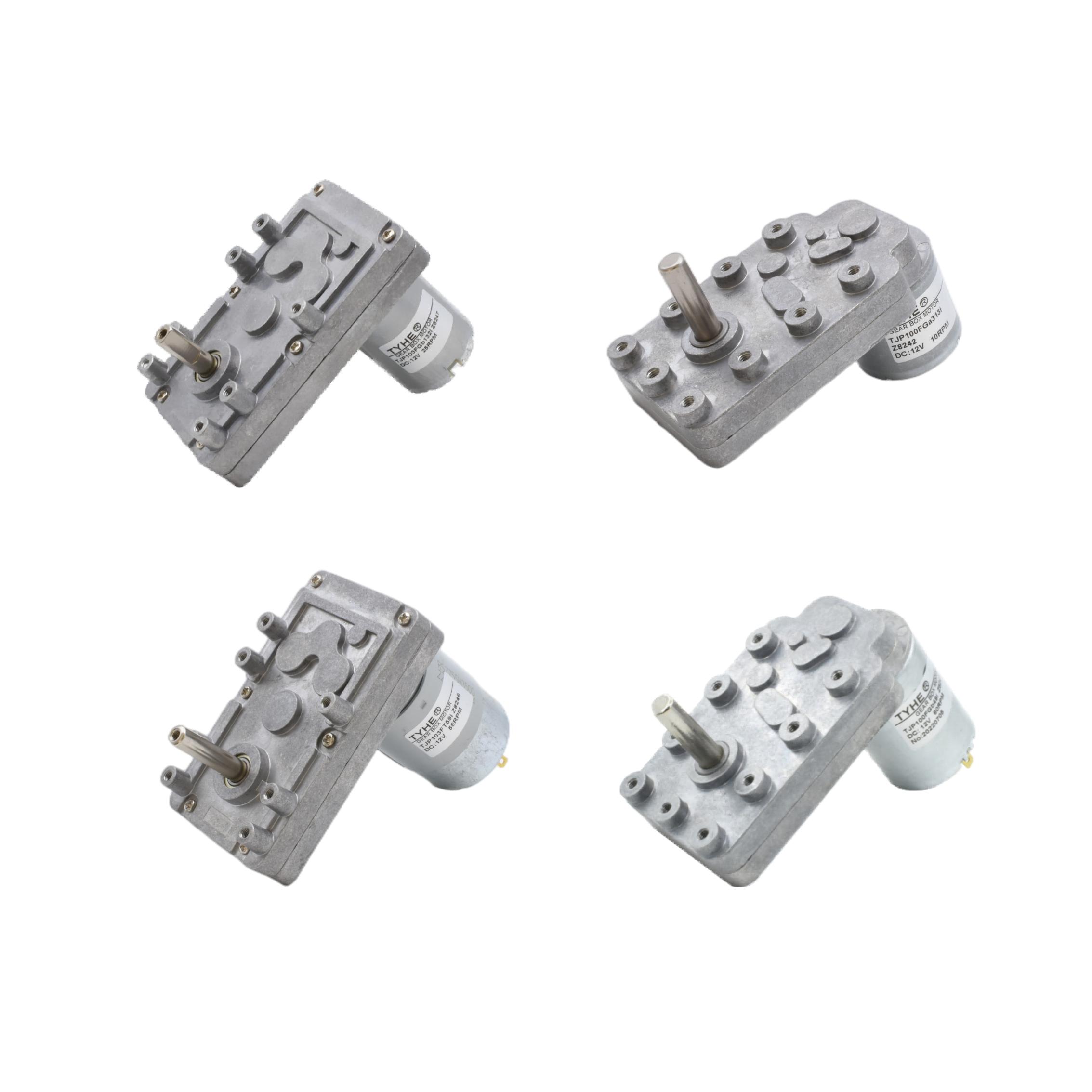
A micro dc motor and a piezo motor can both create controlled motion in compact equipment, but they work in fundamentally different ways. Comparing a micro dc motor with a piezo actuator means looking beyond size: one produces rotation, while the other typically creates small movements through material deformation. The best fit depends on the movement, force, accuracy, and operating conditions your design requires.
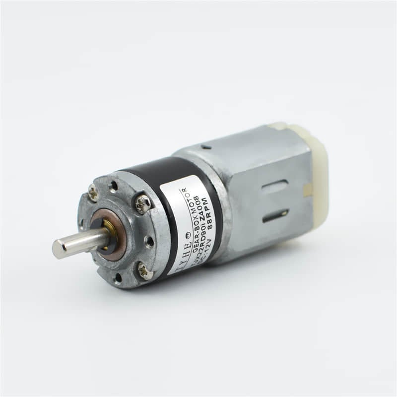
This comparison focuses on the engineering decisions that separate these actuator types: motion profile, control approach, load behavior, and integration effort. A micro dc motor may suit a mechanism needing continuous rotary output, whereas a piezo motor may suit a compact positioning task requiring fine incremental movement. Understanding those differences helps teams choose from requirements instead of relying on a single specification.
How Their Motion and Output Differ
Operating principles shape the movement
A micro dc motor converts electrical energy into shaft rotation through electromagnetic interaction. That rotary output can directly drive a wheel or fan, or move a linear mechanism through a gear train, lead screw, or linkage. A micro dc motor is therefore a practical starting point when the design needs repeatable rotation or motion over a longer travel range.
A piezo motor uses the expansion and contraction of piezoelectric material, often with a frictional or resonant mechanism, to create movement. The actuator advances through small steps or vibration-driven motion rather than conventional electromagnetic shaft rotation. Compared with a micro dc motor, it may offer a different path to positioning in applications where compact movement and fine adjustment matter.
These mechanisms make the output format an early decision point. If the assembly needs a rotating shaft, a micro dc motor provides a direct match, though transmission components may be needed to adjust speed or torque. If the requirement centers on small controlled displacement, a piezo design may be more suitable, subject to its stroke and load limits.
Speed, travel, and positioning requirements
A micro dc motor can maintain rotation for as long as power and operating conditions permit, making it useful for pumps, miniature drives, and moving mechanisms. Gear reduction can trade speed for torque, while a screw or linkage can translate rotation into linear travel. A micro dc motor system may also require feedback when accurate position matters.
Piezo motors are often considered for short travel, incremental positioning, or movements that demand fine adjustment. Their achievable travel and speed depend on actuator construction, drive signal, and applied load. A micro dc motor may reach a longer mechanical travel through transmission, but its practical positioning resolution depends on gearing, feedback, friction, and control design.
When comparing motion profiles, define the full movement rather than only the desired resolution. A micro dc motor can suit repeated continuous cycles, while piezo actuation can suit localized movement with frequent small corrections. Evaluate total stroke, settling behavior, cycle rate, and required accuracy under the real load before choosing either approach.
Control, Load, and Operating Tradeoffs
Control electronics and feedback
A basic micro dc motor can be controlled by changing voltage or using pulse-width modulation, with direction control provided by suitable drive circuitry. For closed-loop positioning, designers may add an encoder or other position sensor. The sensor, control algorithm, and mechanical transmission all influence how a micro dc motor performs in a precision application.
Piezo motors usually need a specialized driver that supplies the voltage waveform and frequency required by the actuator. Control may involve step commands or feedback, depending on the design and positioning target. In contrast, a micro dc motor commonly uses familiar drive methods, but that simplicity does not remove the need to manage startup current, speed variation, or positional feedback.
The control choice affects both circuit design and system commissioning. A micro dc motor can integrate readily where the team already supports brushed motor drives, but the control loop must account for inertia and mechanical play. Piezo systems may require additional driver expertise, so assess board space, electrical interfaces, software effort, and calibration needs together.
Force, load, and duty cycle
A micro dc motor’s usable output depends on its torque-speed behavior, gearing, thermal limits, and the load applied at the shaft. Starting torque and continuous operation should be checked against the actual duty cycle, not treated as interchangeable ratings. A micro dc motor that is overloaded may run hot, slow down, or wear prematurely.
Piezo actuator force and displacement are also linked: the output available at a given stroke depends on the specific design and applied load. Mounting stiffness and contact conditions can influence performance. Compared with a micro dc motor, a piezo motor may suit a different force-and-travel balance, so validate the load at the required position.
Operating environment can change the comparison. A micro dc motor may produce audible noise, vibration, or electromagnetic interference that matters in sensitive equipment, while bearings, brushes, and gears can affect service needs. Piezo assemblies have their own mechanical and electrical constraints. Test both concepts at expected temperature, orientation, vibration, and cycle frequency before committing.
Choosing and Integrating the Right Actuator
Match the actuator to the mechanism
Start by translating the application into measurable requirements: rotary or linear output, travel, speed, load, accuracy, available power, and service life. A micro dc motor often becomes a strong candidate when continuous rotation or a driven mechanism is central. Piezo actuation deserves consideration when short, controlled positioning is the dominant need.
Next, map the actuator into the full mechanical assembly. A micro dc motor may need brackets, a shaft coupling, reduction gears, or a screw to deliver the required motion. Those additions affect backlash, package size, and efficiency. A piezo motor may reduce some transmission needs, but its mounting and preload requirements must fit the surrounding structure.
The most useful comparison is between complete motion systems, not isolated actuators. Include the motor, driver, sensors, transmission, mounts, and control software in each concept. A micro dc motor that appears simple at component level may require feedback hardware, while a piezo motor may shift effort toward high-voltage electronics and mechanical setup.
Verify fit through design testing
Build a test plan around the duty cycle and worst-case load. Measure the movement that matters, such as travel time, repeatability, holding behavior, noise, or temperature rise. A micro dc motor prototype should be tested with its intended gearing and controller, because unloaded shaft results will not represent assembled operation.
For a piezo concept, test the specified driver and mounting arrangement under the expected load and motion sequence. Compare repeatability over repeated cycles, not just initial movement. For a micro dc motor, include startup, reversal, stall protection, and wear considerations where relevant. These checks reveal whether performance remains adequate in the actual system.
Make the final selection against documented acceptance criteria. Choose a micro dc motor when rotary output, continuous motion, or a transmission-based mechanism aligns with the design. Choose a piezo approach when its motion characteristics meet the positioning need and the electronics and mounting can be accommodated. The right choice is the one that satisfies system requirements with manageable integration risk.
FAQ
Is a micro dc motor suitable for precise positioning?
Yes, a micro dc motor can support precise positioning when paired with suitable feedback, control, and mechanical transmission. Accuracy depends on the complete system, including backlash and load. A micro dc motor without position sensing may not provide the repeatability a closed-loop application requires.
When is a piezo motor preferable to a micro dc motor?
A piezo motor may be preferable when the application needs fine incremental motion or a compact positioning solution within its available stroke and load range. A micro dc motor is often a more natural fit for continuous rotary output. Compare their complete mechanisms and drivers against the same operating requirements.
What should engineers test before selecting either motor?
Test actual travel, load, duty cycle, control response, thermal behavior, and mounting conditions. A micro dc motor should be evaluated with the planned transmission and feedback, while a piezo motor needs its intended driver and fixture. Validate the system against measurable acceptance criteria before design release.
