
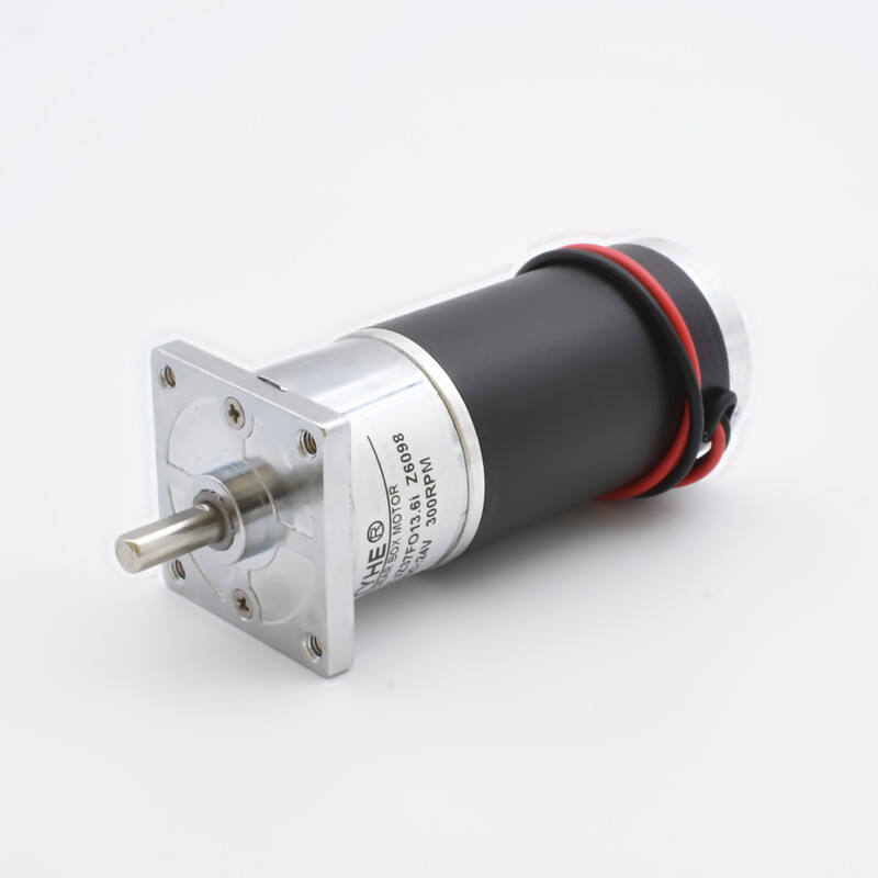
Understanding the fundamentals of DC gear motors is essential for engineers and professionals working in industrial automation, robotics, and mechanical systems. A dc gear motor combines a direct current motor with a gear reduction system, creating a powerful solution that delivers high torque at lower speeds while maintaining precise control characteristics. This integration makes dc gear motor technology particularly valuable in applications requiring controlled movement, consistent power delivery, and reliable operation under varying load conditions.
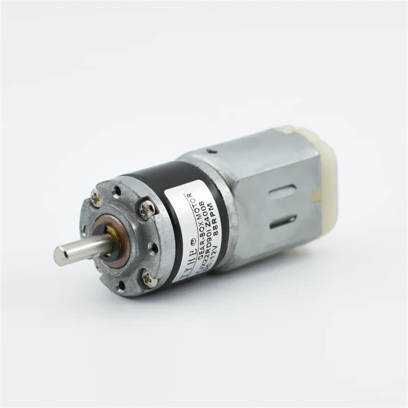
The widespread adoption of dc gear motor systems across manufacturing, packaging, conveyor systems, and automated machinery demonstrates their versatility and effectiveness in industrial environments. Unlike standard DC motors that operate at high speeds with relatively low torque, a dc gear motor leverages mechanical advantage through gear reduction to transform high-speed, low-torque input into low-speed, high-torque output. This fundamental characteristic makes these motors indispensable for applications where precise positioning, controlled speed, and substantial mechanical force are required for optimal system performance.
Core Components and Operating Principles
DC Motor Foundation Elements
The dc gear motor begins with a standard direct current motor as its primary power source. This DC motor consists of a stator containing permanent magnets or electromagnets, an armature with copper windings, and a commutator system that ensures continuous rotation. When electrical current flows through the armature windings within the magnetic field, it creates rotational force according to electromagnetic principles. The dc gear motor design capitalizes on this reliable electromagnetic conversion while addressing the typical limitations of high-speed, low-torque DC motor output.
The brushed dc gear motor configuration includes carbon brushes that maintain electrical contact with the commutator segments, enabling current direction changes that sustain continuous rotation. Alternatively, brushless dc gear motor designs eliminate physical brush contact through electronic switching, offering improved efficiency and reduced maintenance requirements. Both configurations provide the foundational rotational energy that the gear reduction system subsequently modifies to meet specific torque and speed requirements for industrial applications.
Gear Reduction Mechanism
The gear reduction system represents the defining characteristic that transforms a basic DC motor into a specialized dc gear motor. This mechanical arrangement typically consists of multiple gear stages, each contributing to the overall reduction ratio. Common gear types include spur gears, planetary gears, and worm gears, with each configuration offering distinct advantages for specific applications. The gear reduction ratio directly determines the relationship between input speed and output speed, as well as the corresponding torque multiplication factor.
In a typical dc gear motor design, the motor shaft connects to the input gear, which meshes with progressively larger gears through multiple reduction stages. Each gear stage multiplies torque while proportionally reducing speed according to the gear ratio. For example, a 10:1 reduction ratio means the output shaft rotates once for every ten input shaft rotations while providing approximately ten times the input torque. This mechanical advantage allows the dc gear motor to handle substantial loads that would overwhelm a direct-drive DC motor.
Integration and Housing Design
Modern dc gear motor units integrate the motor and gear components within a unified housing that protects internal mechanisms while providing standardized mounting interfaces. The housing design must accommodate thermal management requirements, as both the DC motor and gear friction generate heat during operation. Effective thermal design ensures consistent performance and extends operational life in demanding industrial environments where dc gear motor systems operate continuously under varying load conditions.
The integration approach affects overall dc gear motor performance characteristics, including backlash, efficiency, and mechanical precision. High-quality designs minimize gear backlash through precise manufacturing tolerances and appropriate gear tooth profiles. The housing also incorporates sealing systems that protect internal components from contamination while allowing for thermal expansion and lubrication maintenance. These design considerations directly impact the reliability and maintenance requirements of dc gear motor installations in industrial settings.
Performance Characteristics and Specifications
Torque and Speed Relationships
The fundamental performance advantage of a dc gear motor lies in its ability to provide high torque output at controlled speeds. Unlike direct-drive motors that operate at thousands of RPM with limited torque capacity, a dc gear motor can deliver substantial torque at speeds ranging from a few RPM to several hundred RPM, depending on the gear reduction ratio. This torque-speed relationship makes dc gear motor technology ideal for applications requiring precise positioning, controlled acceleration, and the ability to maintain position under load.
Torque characteristics vary significantly based on the gear reduction ratio, motor size, and electrical input parameters. A typical dc gear motor specification includes rated torque, stall torque, and continuous torque values that define operational limits and performance capabilities. The gear reduction multiplies the base motor torque by the reduction ratio, though some efficiency loss occurs through gear friction and mechanical losses. Understanding these torque specifications enables proper dc gear motor selection for specific load requirements and duty cycles.
Efficiency and Power Considerations
Efficiency represents a critical performance parameter for dc gear motor systems, particularly in applications requiring continuous operation or battery power. Overall system efficiency depends on both motor efficiency and gear train efficiency, with typical dc gear motor units achieving 70-90% efficiency depending on design quality and operating conditions. Higher gear reduction ratios generally result in lower efficiency due to increased mechanical losses through multiple gear stages.
Power requirements for a dc gear motor depend on the mechanical load, operating speed, and duty cycle characteristics. The motor must provide sufficient power to overcome both the external load and internal friction losses while maintaining adequate thermal margins. Proper power sizing ensures reliable operation without overheating or performance degradation. Many dc gear motor applications benefit from variable speed control, which allows optimization of power consumption based on changing load requirements and operational conditions.
Control and Response Characteristics
Control characteristics distinguish dc gear motor systems from other motor technologies, particularly in applications requiring precise speed regulation or position control. The inherent linear relationship between applied voltage and motor speed provides predictable control behavior that simplifies integration with electronic control systems. Additionally, the high torque capability of a dc gear motor enables rapid acceleration and deceleration while maintaining precise positioning accuracy.
Response time and dynamic behavior of dc gear motor systems depend on the mechanical inertia of both the motor and gear components, as well as the connected load. Lower gear ratios typically provide faster response times but reduced torque multiplication. The control system design must account for these dynamic characteristics to achieve optimal performance in closed-loop positioning or speed control applications where dc gear motor precision is essential.
Industrial Applications and Use Cases
Manufacturing and Automation Systems
Manufacturing environments extensively utilize dc gear motor technology for conveyor systems, assembly line components, and automated machinery where precise control and reliable operation are essential. In conveyor applications, a dc gear motor provides the torque necessary to move heavy loads while maintaining consistent speed control for proper material handling timing. The ability to vary speed and direction makes dc gear motor systems particularly valuable for complex material handling sequences that require synchronized movement between multiple conveyor sections.
Automated assembly systems rely on dc gear motor precision for positioning components, operating actuators, and controlling feed mechanisms. The high torque capability enables these systems to handle varying load conditions while maintaining positional accuracy required for quality assembly operations. Many manufacturing processes benefit from the ability to program specific speed profiles and positioning sequences that optimize production efficiency while ensuring consistent product quality through precise dc gear motor control.
Robotics and Precision Positioning
Robotics applications represent one of the most demanding uses for dc gear motor technology, requiring precise positioning, smooth motion control, and reliable operation under varying load conditions. Industrial robots use multiple dc gear motor units for joint actuation, providing the torque and precision necessary for accurate manipulation tasks. The gear reduction enables robots to handle substantial payloads while maintaining the fine positioning control required for assembly, welding, and material handling operations.
Precision positioning systems in CNC machinery, 3D printers, and laboratory equipment depend on dc gear motor characteristics for accurate movement control. These applications require the combination of high torque for acceleration and holding, precise speed control for smooth motion, and minimal backlash for positioning accuracy. The dc gear motor design addresses these requirements through appropriate gear selection, quality manufacturing, and integration with sophisticated control electronics that optimize performance for specific positioning tasks.
Packaging and Processing Equipment
Packaging machinery extensively employs dc gear motor systems for form-fill-seal operations, labeling systems, and product handling mechanisms where timing and torque control are critical. These applications often require intermittent motion with precise stopping positions, making the controllability of a dc gear motor ideal for coordinating multiple packaging operations. The ability to provide high starting torque ensures reliable operation even when machinery has been idle and may have increased friction due to material buildup or environmental conditions.
Food processing and pharmaceutical equipment utilize dc gear motor technology for mixing, conveying, and dosing applications where sanitary design and precise control are essential. The sealed housing designs protect internal components from washdown procedures while providing the torque and speed control necessary for consistent processing operations. Many dc gear motor units designed for these applications include special coatings and materials that meet industry hygiene standards while maintaining reliable mechanical performance.
Selection Criteria and Design Considerations
Load Analysis and Torque Requirements
Proper dc gear motor selection begins with comprehensive analysis of the mechanical load characteristics, including starting torque, running torque, and peak torque requirements throughout the operating cycle. The load analysis must consider factors such as friction, inertia, external forces, and any mechanical advantage provided by pulleys, screws, or linkages in the driven system. Understanding these load characteristics enables selection of a dc gear motor with appropriate torque capacity and gear reduction ratio for reliable operation without overloading.
Dynamic load conditions require careful consideration of acceleration and deceleration requirements, as these transient conditions often demand higher torque than steady-state operation. The dc gear motor must provide sufficient torque margin to handle peak loads while maintaining thermal limits during continuous operation. Safety factors typically range from 1.5 to 3.0 times the calculated load requirements, depending on the criticality of the application and the consequences of motor failure or performance degradation.
Speed and Positioning Requirements
Speed requirements directly influence dc gear motor selection through the relationship between motor base speed and required gear reduction ratio. Applications requiring very low speeds necessitate higher gear reduction ratios, which may impact efficiency and response time but provide increased torque capability. Conversely, applications requiring higher speeds with moderate torque may benefit from lower gear ratios that provide better efficiency and faster response characteristics.
Positioning accuracy requirements affect both gear selection and overall dc gear motor design considerations. Applications demanding high positioning accuracy require gear systems with minimal backlash and high mechanical precision. Some applications may require encoder feedback for closed-loop position control, necessitating dc gear motor designs that accommodate feedback devices without compromising mechanical integrity or adding excessive complexity to the control system.
Environmental and Operational Factors
Environmental conditions significantly impact dc gear motor design requirements, including temperature range, humidity, contamination exposure, and mounting orientation constraints. High-temperature applications may require special motor windings, bearing materials, and lubricants to ensure reliable operation. Similarly, applications exposed to moisture, chemicals, or abrasive particles require appropriate sealing and housing materials that protect internal components while maintaining accessibility for maintenance procedures.
Duty cycle characteristics influence both motor selection and thermal design requirements for dc gear motor applications. Continuous duty applications require motors designed for heat dissipation and thermal stability, while intermittent duty applications may allow higher peak performance with appropriate cooling periods. Understanding the operational profile enables optimization of dc gear motor selection for cost-effectiveness while ensuring adequate performance margins for the intended application requirements.
FAQ
What is the main advantage of using a dc gear motor instead of a regular DC motor?
The primary advantage of a dc gear motor is its ability to provide high torque at low speeds through mechanical gear reduction. While a standard DC motor operates at high speeds with relatively low torque, the gear reduction system multiplies the torque output while reducing speed, making it ideal for applications requiring substantial mechanical force, precise positioning, and controlled movement. This combination enables the dc gear motor to handle heavy loads and provide precise control that would be difficult to achieve with a direct-drive DC motor.
How does gear reduction ratio affect dc gear motor performance?
The gear reduction ratio directly determines the relationship between speed and torque in a dc gear motor system. A higher reduction ratio provides greater torque multiplication but reduces output speed and typically decreases overall efficiency due to additional mechanical losses. For example, a 50:1 reduction ratio provides approximately 50 times more torque than the base motor while reducing speed by the same factor. The optimal reduction ratio depends on the specific application requirements for speed, torque, and positioning accuracy.
What maintenance is required for dc gear motor systems?
Maintenance requirements for dc gear motor systems typically include periodic lubrication of gear components, inspection of brushes and commutator in brushed designs, and monitoring of bearing condition. The gear reduction system requires appropriate lubrication to minimize wear and maintain efficiency, with lubrication intervals depending on operating conditions and manufacturer recommendations. Brushed dc gear motors require periodic brush replacement, while brushless designs generally require less maintenance but may need electronic controller servicing. Regular inspection of mounting, coupling, and electrical connections helps ensure reliable long-term operation.
Can dc gear motors be used for precise positioning applications?
Yes, dc gear motors are well-suited for precise positioning applications when properly selected and configured. The gear reduction provides mechanical advantage for holding position under load, while the linear voltage-to-speed relationship of DC motors enables predictable control characteristics. For high-precision applications, factors such as gear backlash, encoder resolution, and control system design become critical. Many dc gear motor systems incorporate encoders or other feedback devices to enable closed-loop position control with high accuracy and repeatability suitable for robotics, CNC machinery, and automated positioning systems.
