
 EN
EN
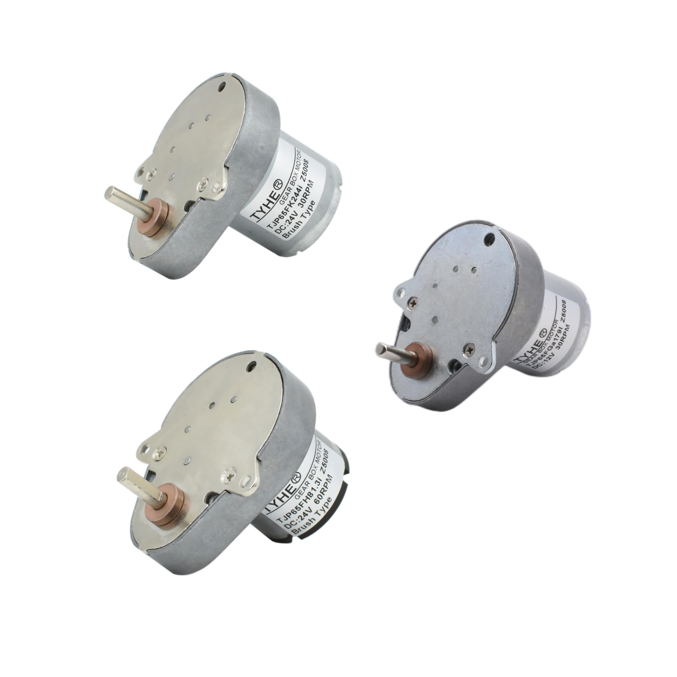
A brush dc motor is one of the most widely used electromechanical devices in both industrial and commercial applications. Its enduring popularity stems from a straightforward operating principle, ease of speed control, and a proven track record that spans well over a century of engineering development. Whether powering conveyor systems, robotics, automotive accessories, or precision instruments, the brush dc motor continues to hold a respected position in modern drive systems where simplicity, reliability, and cost-effectiveness are valued above all else.
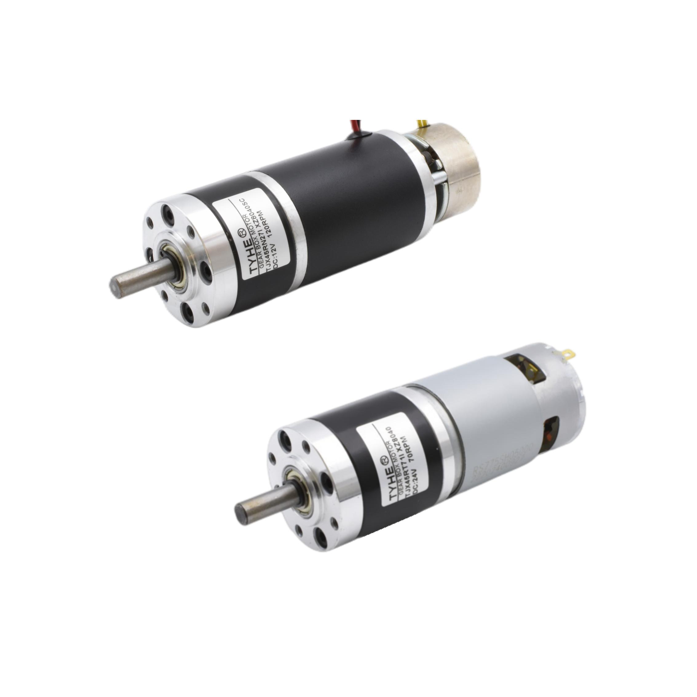
Understanding the inner workings of a reliable brush dc motor requires more than a surface-level description of its parts. It demands a thorough look at how each component contributes to mechanical output, how electrical energy is transferred and converted, and why specific design choices make the difference between a motor that lasts years under demanding conditions and one that fails prematurely. This article breaks down the core mechanisms, materials, and engineering principles that define a well-built brush dc motor, giving engineers, procurement managers, and product designers the insight they need to make informed decisions.
The Fundamental Architecture of a Brush DC Motor
Stator: The Magnetic Foundation
The stator is the stationary outer shell of a brush dc motor, and its primary function is to create a fixed magnetic field through which the rotor can rotate. In smaller or lower-cost motors, the stator typically uses permanent magnets, while larger or more powerful motors often employ field windings that allow adjustable magnetic flux. The quality and material composition of the stator directly influences how efficiently the motor converts electrical input into mechanical output.
Permanent magnet stators, commonly found in modern compact brush dc motor designs, use materials such as ferrite, alnico, or rare-earth magnets like neodymium. Each material offers a different trade-off between magnetic strength, temperature stability, and cost. A well-engineered stator ensures that the magnetic field remains consistent and uniform, minimizing energy losses and contributing to stable motor performance across varying load conditions.
The housing of the stator also serves a structural purpose, providing mechanical support and protecting internal components from dust, moisture, and physical damage. Many industrial-grade brush dc motor units feature a robust cast iron or steel housing that enhances both durability and thermal dissipation, both of which are critical for long operational life.
Rotor and Armature Windings
The rotor, also called the armature, is the rotating core of the brush dc motor. It consists of a laminated iron core wound with copper coils arranged in a specific pattern to produce maximum torque when energized. The laminations are thin sheets of magnetic steel stacked together, a design choice that significantly reduces eddy current losses and keeps the motor running efficiently at higher speeds.
The armature windings in a reliable brush dc motor are connected to the commutator at precise intervals. The number of coils, the winding pattern, and the thickness of the copper wire all influence the torque output, back-EMF characteristics, and heat generation of the motor. A motor designed for continuous industrial operation will typically use heavier gauge copper wire and a higher slot count to distribute the magnetic load more evenly and reduce hot spots.
Proper insulation of the armature windings is equally critical. In demanding environments, winding insulation rated for high temperature classes such as Class F or Class H ensures the motor can handle elevated operating temperatures without insulation breakdown, which is a leading cause of motor failure. Investing in superior armature construction is what separates a truly dependable brush dc motor from a commodity unit.
The Role of the Commutator and Brush System
Commutator Mechanics and Current Switching
The commutator is arguably the most defining component of any brush dc motor, and it is the element that distinguishes this motor type from its brushless counterpart. The commutator is a cylindrical assembly of copper segments mounted on the rotor shaft, each segment insulated from the others by thin mica or resin spacers. As the rotor spins, the commutator rotates with it, and the brushes maintain sliding contact with these segments to deliver current to successive armature coils.
This mechanical switching of current ensures that the electromagnetic torque produced by the armature is always aligned in the same rotational direction, allowing continuous rotation. The precision with which the commutator segments are machined and aligned is critical to smooth operation. Any eccentricity, surface irregularity, or contamination on the commutator surface can lead to increased electrical noise, uneven brush wear, and ultimately reduced motor life.
A high-quality commutator in a reliable brush dc motor is ground and polished to a fine tolerance after assembly. Some designs also include riser connections — the points where armature coils connect to commutator segments — that are brazed rather than soldered, providing superior mechanical and electrical integrity under vibration and thermal cycling.
Brush Materials and Contact Dynamics
The brushes in a brush dc motor are the sliding electrical contacts that ride against the commutator to transfer current between the stationary circuit and the rotating armature. They are typically made from carbon, graphite, electrographite, or metal-graphite composite materials, with each grade suited to different operating conditions. Carbon brushes provide moderate current density and good commutation characteristics, while electrographite brushes are preferred for higher-speed and higher-temperature applications.
The brush grade selection profoundly affects both motor performance and maintenance intervals. A brush material that is too hard can cause excessive commutator wear, while one that is too soft may wear down rapidly itself, requiring frequent replacement. In a well-designed brush dc motor, the brush grade is carefully matched to the commutator material, operating speed, current density, and environmental conditions to achieve the optimal balance of low contact resistance, minimal wear, and stable commutation.
The brush holders maintain consistent spring pressure against the commutator, which is essential for reliable electrical contact. Too little pressure causes arcing and increased contact resistance; too much leads to accelerated mechanical wear. Precision-machined brush holders with calibrated springs are a hallmark of a motor built for long-term reliability, and they represent a detail that is often overlooked in lower-quality designs.
Energy Conversion and Torque Generation
Electromagnetic Interaction Inside the Motor
The fundamental operating principle of a brush dc motor is based on the interaction between a magnetic field and a current-carrying conductor. When electrical current flows through the armature windings situated within the stator's magnetic field, a force is exerted on those conductors according to the Lorentz force law. This force creates a torque that causes the rotor to spin, converting electrical energy into mechanical rotational energy.
The direction of this torque is determined by both the direction of current flow and the orientation of the magnetic field, which is why reversing the input polarity of a brush dc motor will reverse its rotational direction. This straightforward speed and direction controllability is one of the primary reasons the brush dc motor remains popular in applications requiring precise motion control, such as robotics, CNC equipment, and automotive actuators.
As the motor accelerates and the armature rotates, it generates a back electromotive force, commonly referred to as back-EMF. This back-EMF opposes the applied voltage and naturally limits motor speed under no-load conditions. The relationship between applied voltage, back-EMF, armature resistance, and load torque forms the governing equations of brush dc motor performance, and understanding this relationship is essential for selecting the right motor for a given application.
Thermal Management and Efficiency Factors
Thermal management is a critical aspect of reliable brush dc motor operation. Heat is generated through several mechanisms: resistive losses in the armature windings, iron losses in the laminated core, friction losses at the brush-commutator interface, and bearing friction. If this heat is not adequately dissipated, winding insulation degrades, lubricants break down, and motor life is significantly shortened.
Well-engineered motors address thermal management through a combination of design choices. Ventilation channels within the motor housing, external cooling fins, forced-air cooling systems, and thermally conductive mounting arrangements all contribute to effective heat dissipation. In high-duty-cycle applications, a brush dc motor with a built-in thermal protection device such as a PTC thermistor or thermal cutoff switch can prevent damage from unexpected overload conditions.
Efficiency in a brush dc motor is closely linked to the quality of its construction. Low-resistance armature windings, high-grade magnetic materials, precision bearings with correct lubrication, and well-fitted brush contact systems all work together to minimize energy losses. For industrial buyers and design engineers, total efficiency is not merely an environmental concern — it directly impacts operating costs, heat generation, and the sizing of power supply systems.
Bearing Systems and Mechanical Durability
Bearing Selection and Load Handling
Bearings are the silent workhorses of a reliable brush dc motor, supporting the rotor shaft and allowing it to spin smoothly under both radial and axial loads. The two most common bearing types used in brush dc motors are ball bearings and sleeve (plain) bearings. Ball bearings offer lower friction, higher load capacity, and better performance at higher speeds, making them the preferred choice for most industrial and precision applications.
Sleeve bearings, made from sintered bronze or other oil-impregnated materials, are simpler and quieter but are better suited for lower-speed, lighter-load applications. The choice between these bearing types in a brush dc motor depends heavily on the intended duty cycle, rotational speed, load characteristics, and acceptable maintenance frequency. A motor specified for continuous high-load operation will almost always use precision ball bearings preloaded to eliminate axial play.
The quality of bearing seals and lubrication is equally important. Sealed or shielded bearings prevent contamination ingress in dirty or dusty environments, while the correct lubricant grade ensures consistent rolling element performance across a wide temperature range. Bearing failure is one of the most common reasons for motor replacement, so investing in well-specified bearings at the design stage is a key element of building a brush dc motor with a long service life.
Shaft Design and Mechanical Integration
The rotor shaft of a brush dc motor must be designed to transmit the generated torque to the load without deflection, fatigue, or surface wear at the coupling interface. Shafts are typically machined from medium-carbon steel or alloy steel, hardened and ground at the bearing journals and output end to precise dimensional tolerances. Key ways, flat sections, or threaded ends are machined into the shaft depending on how the motor will be coupled to its driven load.
Shaft runout, which refers to any eccentricity or wobble in the rotating shaft, must be held to tight tolerances in a well-built brush dc motor. Excessive runout increases vibration, accelerates bearing wear, and can cause premature failure of downstream components such as gearboxes or couplings. A reliable brush dc motor manufacturer will specify maximum shaft runout values and verify them during quality inspection before the motor ships.
Proper alignment between the motor shaft and the driven load is a responsibility shared between the motor manufacturer and the system integrator. However, a motor with a precisely machined mounting flange and shaft provides the best foundation for achieving that alignment. This attention to mechanical detail is what allows a well-designed brush dc motor to deliver thousands of hours of trouble-free operation even in demanding industrial settings.
Maintenance Considerations and Long-Term Reliability
Brush Inspection and Replacement Cycles
One of the defining maintenance requirements of a brush dc motor is periodic inspection and replacement of the carbon brushes. Because the brushes are consumable contact elements, they gradually wear down as they slide against the commutator. Most manufacturers provide a minimum brush length specification below which the brush must be replaced to prevent the brush spring from contacting the commutator and causing damage.
The rate of brush wear depends on the current density, operating speed, commutator surface condition, environmental humidity, and the specific brush grade used. In a well-maintained brush dc motor, brush replacement intervals might range from several hundred to several thousand operating hours. Keeping a maintenance log and inspecting brushes at regular intervals is a simple but highly effective strategy for preventing unexpected motor failure.
When replacing brushes, it is also good practice to inspect the commutator surface for scoring, uneven wear, or discoloration. A smooth, medium-brown patina on the commutator is a sign of healthy operation, while black deposits, grooving, or copper buildup indicate problems that need to be investigated and corrected before the motor is returned to service. This kind of proactive maintenance is what extends the practical service life of a brush dc motor well beyond initial expectations.
Environmental Protection and Storage Practices
The operating environment significantly influences how long a brush dc motor remains in reliable service. Exposure to excessive moisture, corrosive gases, abrasive dust, or extreme temperatures can accelerate the degradation of insulation, bearings, brushes, and commutator surfaces. Motors intended for use in harsh environments are typically assigned an IP rating that indicates the degree of protection against dust and liquid ingress, and selecting the correct IP-rated motor for the application is a fundamental reliability decision.
Storage conditions matter too. A brush dc motor that is stored in a humid environment for an extended period before installation can absorb moisture into the winding insulation, lowering its dielectric strength and increasing the risk of insulation failure when the motor is first energized. Proper storage in a dry, temperature-controlled environment, combined with periodic insulation resistance testing before commissioning stored motors, is best practice for ensuring that the motor performs reliably from the first moment of operation.
Protective coatings on the commutator, rust-inhibiting treatments on ferrous shaft surfaces, and sealed bearing arrangements all contribute to a more resilient brush dc motor in adverse conditions. When specifying a motor for a demanding application, reviewing the manufacturer's environmental and storage specifications is just as important as reviewing the electrical and mechanical performance data.
FAQ
What makes a brush dc motor different from a brushless dc motor?
A brush dc motor uses physical carbon brushes and a mechanical commutator to switch current through the armature windings, while a brushless dc motor relies on electronic commutation through a controller. The brush dc motor is simpler, lower in cost, and easier to control at basic levels, but it requires periodic brush replacement. Brushless motors offer longer service life and higher efficiency but need more sophisticated drive electronics and are generally more expensive to procure and integrate.
How do I determine the right brush dc motor for my application?
Selecting the right brush dc motor involves evaluating the required torque, speed range, duty cycle, supply voltage, physical envelope, and environmental conditions of the application. Start by calculating the load torque and the operating speed, then identify a motor whose rated performance exceeds those requirements with sufficient safety margin. Also consider the motor's thermal class, IP protection rating, bearing type, and available shaft configuration to ensure full mechanical and electrical compatibility with your system.
How long does a brush dc motor typically last?
The service life of a brush dc motor depends heavily on the quality of its construction, the operating conditions, and the maintenance practices applied. Under favorable conditions with regular brush inspection and replacement, a well-built brush dc motor can provide tens of thousands of hours of reliable service. Harsh environments, overloading, inadequate lubrication, or neglected maintenance will significantly reduce that lifespan. Following the manufacturer's maintenance schedule is the most effective way to maximize motor life.
Can a brush dc motor operate in both directions?
Yes, a brush dc motor can be made to rotate in either direction by reversing the polarity of the voltage applied to the armature. This bidirectional capability is one of the practical advantages of the brush dc motor in applications such as positioning systems, actuators, and conveyor drives where reversible motion is required. Reversing the direction is straightforward with a simple H-bridge driver circuit or reversible switch, making the brush dc motor a versatile choice for controlled bidirectional motion applications.
