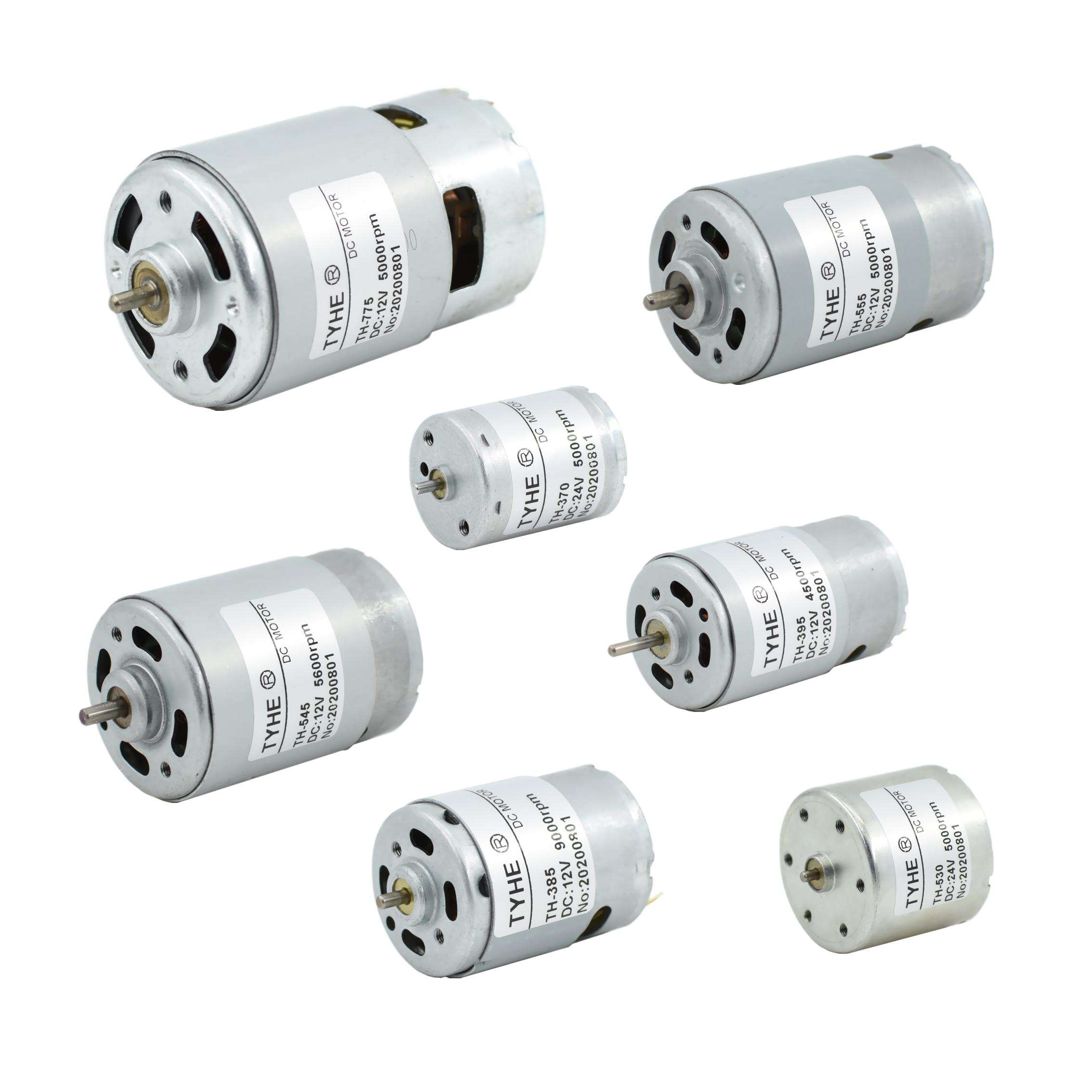
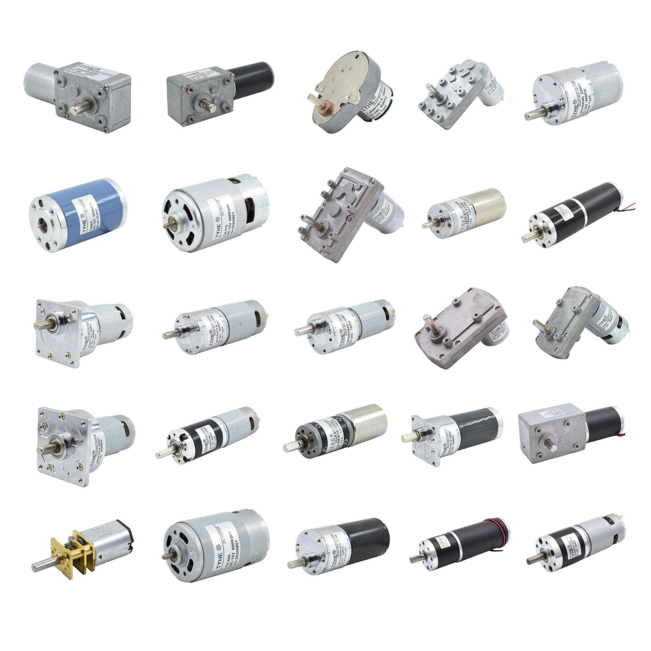
How Does a DC Motor Work?
A DC Motor is one of the most important inventions in the history of electrical engineering, converting direct current electrical energy into mechanical energy. From industrial machinery and transportation systems to home appliances and robotics, it is a key component in countless devices. Understanding how a DC Motor works is essential for engineers, technicians, and anyone interested in electromechanical systems.
This article explains the working principles of a DC Motor, its components, types, and applications, as well as the science behind its operation. We will also cover how torque is generated, the role of commutation, and how speed and direction are controlled.
Basic Principle of Operation
The fundamental working principle of a DC Motor is based on electromagnetism. When a current-carrying conductor is placed within a magnetic field, it experiences a mechanical force. This is described by Fleming’s Left-Hand Rule, which states:
The thumb represents the direction of force (motion).
The first finger represents the magnetic field direction (north to south).
The second finger represents the current direction (positive to negative).
By arranging the conductor in a specific configuration inside the motor, this force can be harnessed to produce continuous rotation.
Main Components of a DC Motor
Armature (Rotor)
The rotating part of the motor that carries current through windings. The armature is mounted on a shaft and interacts with the magnetic field to generate torque.
Commutator
A segmented copper ring connected to the armature windings. Its role is to reverse the direction of current in each armature coil as it rotates, ensuring that torque is always produced in the same direction.
Brushes
Usually made of carbon or graphite, brushes maintain electrical contact between the stationary power supply and the rotating commutator.
Field Winding or Permanent Magnets
These create the stationary magnetic field in which the armature rotates. In some designs, electromagnets are used; in others, permanent magnets provide the field.
Bearings
Support the rotating shaft, reducing friction and enabling smooth motion.
Housing (Frame)
The outer casing that holds the components together, protects them from damage, and may also assist in heat dissipation.

Step-by-Step Working Process
Power Supply Connection
Direct current is supplied to the motor terminals, with the positive and negative leads connected to the brushes.Current Flow Through the Armature
The brushes transmit electrical current into the commutator, which routes it to the armature windings.Magnetic Field Interaction
The current in the armature windings generates its own magnetic field. This interacts with the stationary magnetic field from the field windings or permanent magnets.Force Generation
The interaction between the two magnetic fields produces a force on the armature conductors, causing the rotor to turn.Commutation
As the rotor turns, the commutator reverses the current direction in the armature windings every half rotation. This ensures that the generated torque remains in the same rotational direction.Continuous Rotation
The process repeats continuously as long as the supply voltage is applied, producing sustained mechanical rotation.
Role of Commutation in a DC Motor
Commutation is critical for maintaining smooth rotation. Without reversing the current in the armature windings at the correct time, the torque would change direction and the motor would stop or jerk. In brushed motors, mechanical commutation is performed by the brushes and commutator segments. In brushless designs, electronic circuits perform the commutation.
Types of DC Motors and Their Working Differences
Series Wound DC Motor
The field winding is connected in series with the armature winding.
Produces high starting torque, making it suitable for applications like cranes and electric trains.
Speed varies greatly with load changes.
Shunt Wound DC Motor
The field winding is connected in parallel with the armature winding.
Provides good speed regulation under varying loads.
Common in industrial machinery requiring steady operation.
Compound Wound DC Motor
Combines both series and shunt field windings.
Offers a balance between high starting torque and good speed regulation.
Permanent Magnet DC Motor
Uses permanent magnets for the field instead of windings.
Simpler design, high efficiency, and compact size.
Found in small appliances, toys, and automotive applications.
Brushless DC Motor (BLDC)
Uses electronic commutation instead of brushes.
More efficient, longer lifespan, and less maintenance.
Popular in electric vehicles, drones, and precision instruments.
How a DC Motor Produces Torque
Torque is the rotational force produced by the motor. In a DC Motor, torque depends on:
The strength of the magnetic field.
The amount of current in the armature windings.
The number of active conductors in the magnetic field.
The basic torque equation for a DC Motor is:
T = k × Φ × Ia
Where:
T = Torque
k = Motor constant
Φ = Magnetic flux per pole
Ia = Armature current
Increasing either the armature current or the magnetic flux will increase torque.
Speed Control in a DC Motor
Speed can be controlled by adjusting:
Armature Voltage: Higher voltage increases speed.
Field Current: Increasing field current strengthens the magnetic field and reduces speed; decreasing it increases speed.
PWM Control: Pulse width modulation allows precise and efficient speed adjustments.
Direction Control
The direction of rotation in a DC Motor can be reversed by changing the polarity of either the armature supply or the field supply (but not both simultaneously). This is commonly used in reversible drives such as electric winches and industrial conveyors.
Efficiency Factors
The efficiency of a DC Motor depends on minimizing losses, including:
Electrical losses in windings (resistance losses).
Mechanical losses in bearings and friction.
Core losses due to magnetic hysteresis and eddy currents.
Brushless designs generally offer higher efficiency because they eliminate brush friction and reduce electrical arcing.
Advantages of DC Motors in Practical Use
Precise and smooth speed control.
High starting torque for heavy loads.
Quick response to control signals.
Compatibility with battery power sources.
Limitations to Consider
Maintenance requirements for brushed designs.
Shorter lifespan in high-load conditions if poorly maintained.
Electrical noise from brushes and commutators.
Applications of DC Motors
Transportation: Electric cars, trains, and trams.
Industrial Machinery: Rolling mills, conveyors, and lifts.
Automation: Robotics, CNC machines, and actuators.
Consumer Electronics: Power tools, fans, and household appliances.
The Future of DC Motor Technology
With the rise of renewable energy systems, electric mobility, and advanced automation, the DC Motor remains relevant. Improvements in materials, electronic controllers, and manufacturing methods are enhancing performance, reducing maintenance, and expanding their application range. Brushless DC Motors, in particular, are expected to dominate future designs due to their efficiency and reliability.
Conclusion
A DC Motor works by converting electrical energy from a direct current source into mechanical rotation through the interaction of magnetic fields and current-carrying conductors. The coordinated operation of its components — armature, commutator, brushes, and field system — ensures continuous torque generation. Whether in a brushed or brushless configuration, the DC Motor’s ability to provide precise speed control, high torque, and adaptability keeps it indispensable in many industries.
FAQ
What is the main function of a DC Motor?
Its main function is to convert direct current electrical energy into mechanical rotational energy.
How is the speed of a DC Motor controlled?
By adjusting the armature voltage, field current, or using electronic PWM control.
Why does a DC Motor need a commutator?
The commutator reverses current direction in the armature windings at the right time to maintain continuous rotation in the same direction.
Can a DC Motor run without brushes?
Yes, in brushless DC Motors, electronic circuits replace brushes for commutation.
What determines the torque output of a DC Motor?
Torque is determined by the magnetic flux, armature current, and motor construction.
Table of Contents
- How Does a DC Motor Work?
- Basic Principle of Operation
- Main Components of a DC Motor
- Step-by-Step Working Process
- Role of Commutation in a DC Motor
- Types of DC Motors and Their Working Differences
- How a DC Motor Produces Torque
- Speed Control in a DC Motor
- Direction Control
- Efficiency Factors
- Advantages of DC Motors in Practical Use
- Limitations to Consider
- Applications of DC Motors
- The Future of DC Motor Technology
- Conclusion
- FAQ


