
 EN
EN
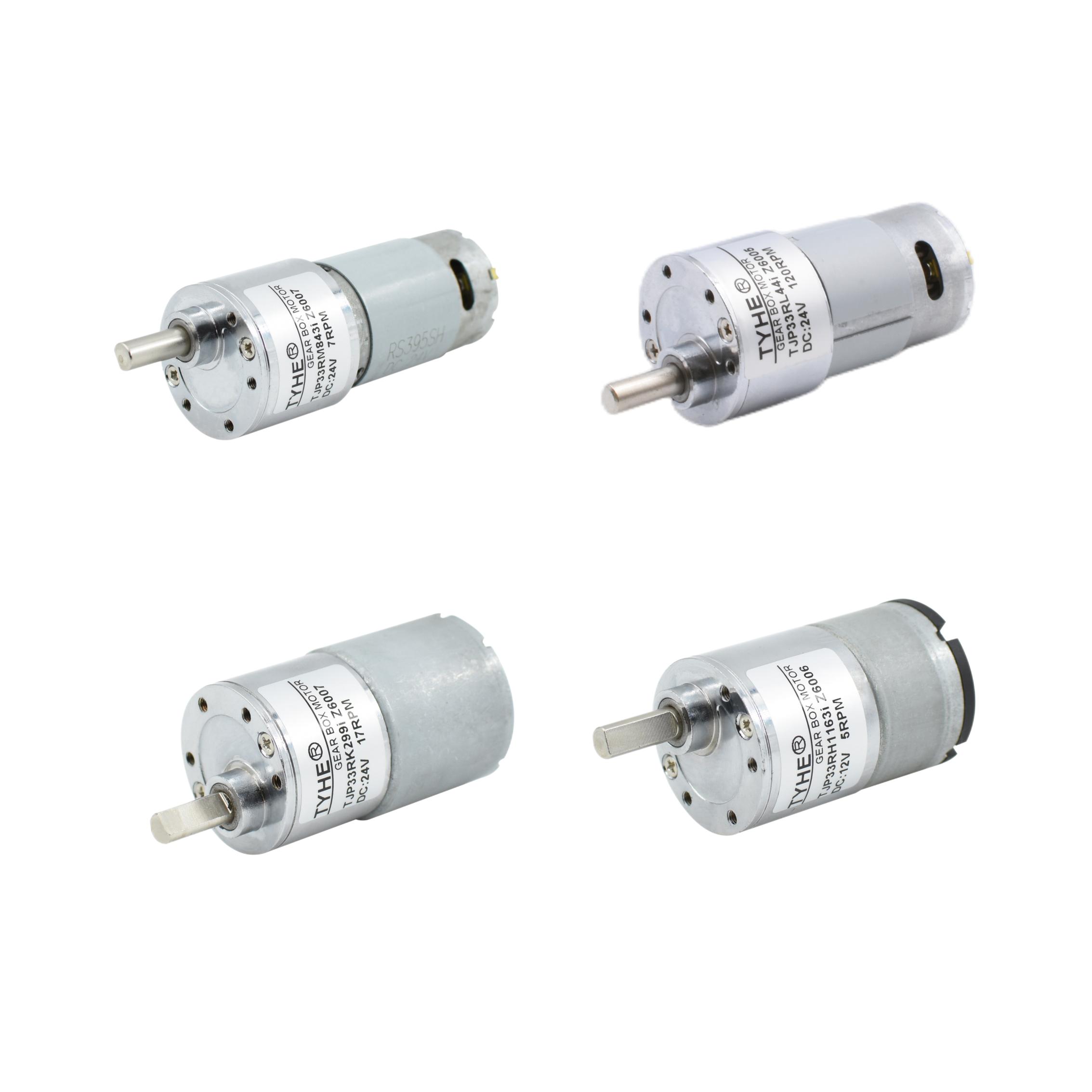
Controlling the speed of a 12v dc motor is one of the most common requirements in industrial automation, robotics, and embedded systems design. Whether you are driving a conveyor belt, a cooling fan, or a precision positioning stage, the ability to vary motor speed without wasting energy is critical. Pulse Width Modulation, commonly called PWM, has become the dominant method for achieving that control efficiently and reliably in a 12v dc motor application.
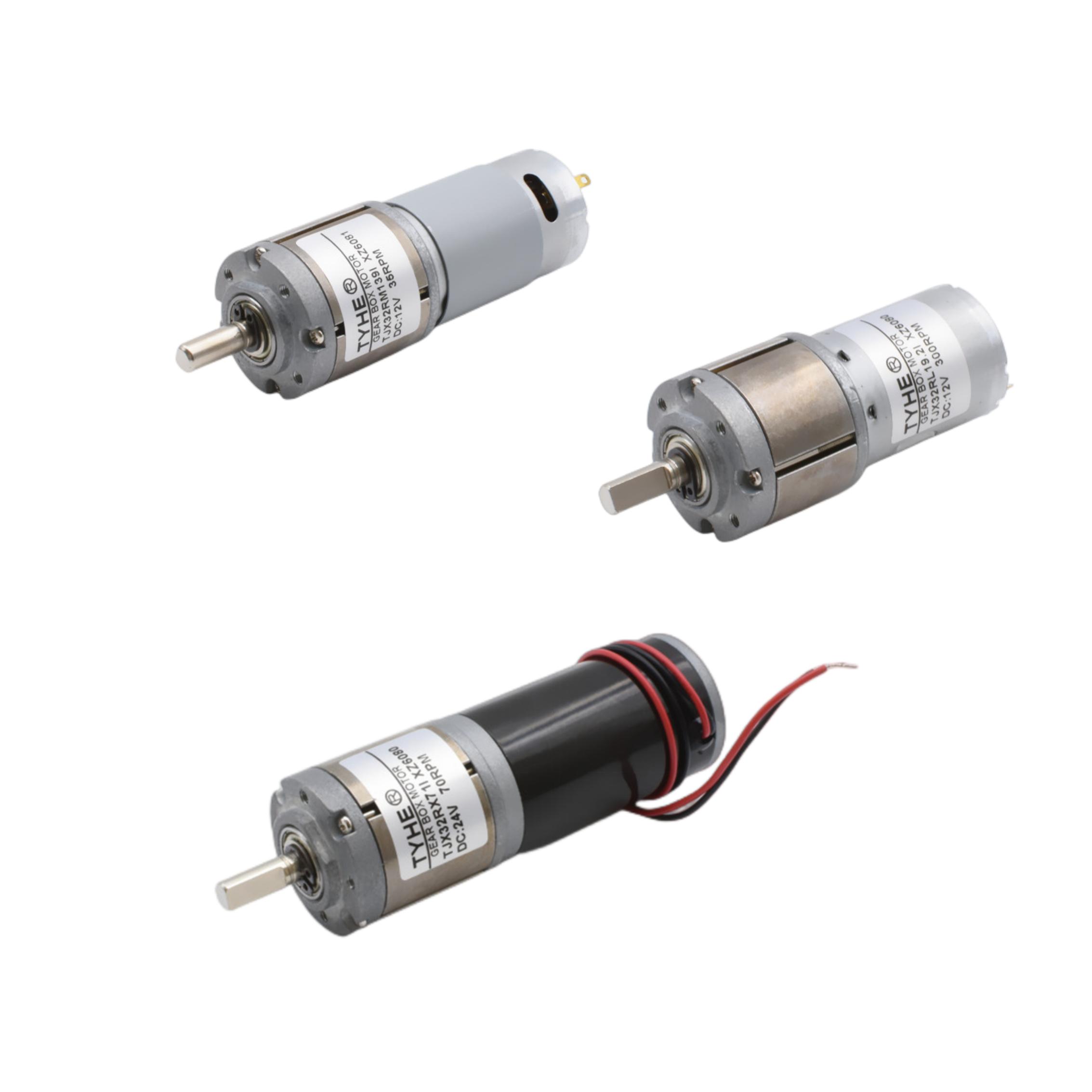
Understanding exactly how PWM interacts with a 12v dc motor helps engineers and designers make smarter decisions about driver circuits, heat management, and overall system performance. This article explains the PWM mechanism, how it benefits 12v dc motor operation, and how to apply it effectively across a range of real-world use cases.
How PWM Controls a 12V DC Motor
The Basic PWM Mechanism
PWM works by switching the supply voltage to the 12v dc motor on and off at a high frequency. Rather than delivering a reduced voltage directly, PWM delivers full voltage pulses at varying widths. The ratio of the on-time to the total period is called the duty cycle. A 50% duty cycle means the 12v dc motor receives voltage for half of each cycle, effectively reducing average power delivered to the motor. A 100% duty cycle means the 12v dc motor runs at full speed, while a 10% duty cycle reduces speed dramatically.
The 12v dc motor itself acts as a low-pass filter due to its winding inductance. The motor does not respond to each individual pulse but instead reacts to the average voltage over time. This means the 12v dc motor shaft rotates smoothly despite the switching nature of the signal, as long as the PWM frequency is high enough relative to the motor's electrical time constant.
Frequency Selection for the 12V DC Motor
Choosing the right PWM frequency for a 12v dc motor is important. At low frequencies, the 12v dc motor may exhibit audible noise, torque ripple, or jerky rotation. Most 12v dc motor applications use PWM frequencies between 1 kHz and 25 kHz. Higher frequencies reduce noise and smooth motor rotation but increase switching losses in the driver transistor. For a standard 12v dc motor, a frequency around 5 kHz to 20 kHz typically offers the best balance between smooth operation and driver efficiency.
Benefits of PWM for 12V DC Motor Applications
Energy Efficiency and Thermal Management
One of the key advantages of using PWM to control a 12v dc motor is energy efficiency. Unlike linear voltage regulators that dissipate excess voltage as heat, a PWM driver switches fully on or fully off. When a MOSFET or transistor is fully on, its resistance is near zero, so power loss is minimal. When it is fully off, no current flows. This means the driver circuit loses very little energy as heat, even when the 12v dc motor runs at reduced speed. For battery-powered systems, this efficiency gain directly translates into longer operating time per charge.
Thermal management of the 12v dc motor itself also improves with PWM. Because the motor windings still receive full-voltage pulses, the magnetic field strength remains strong at low speeds. This helps the 12v dc motor maintain adequate torque even at reduced duty cycles, which prevents the motor from overloading and overheating under moderate loads at low speed settings.
Precise Speed and Torque Control
PWM gives engineers fine-grained control over 12v dc motor speed by simply adjusting the duty cycle in small increments. A microcontroller or dedicated PWM controller can sweep the 12v dc motor from near-zero speed to full speed in smooth, programmable steps. This makes PWM ideal for applications where a 12v dc motor must follow a speed profile, respond to sensor feedback, or operate in a closed-loop control system. PID controllers, for example, pair naturally with PWM-driven 12v dc motor systems to maintain constant speed under varying load conditions.
Practical PWM Implementation for a 12V DC Motor
Driver Circuit Considerations
A 12v dc motor cannot be driven directly from a microcontroller's PWM pin because the motor draws far more current than the pin can supply. A dedicated motor driver IC or a MOSFET-based H-bridge circuit is required. The H-bridge allows the 12v dc motor to be driven in both directions while the PWM signal controls speed. When selecting a driver for a 12v dc motor, pay attention to the continuous current rating, peak current rating, and the maximum PWM frequency the device supports. Gate drive speed also matters, as a slow-switching MOSFET increases switching losses and heat in high-frequency 12v dc motor applications.
Flyback diodes or body diodes in the MOSFET must be capable of handling the inductive kickback generated when the 12v dc motor winding is switched off. Without adequate protection, these voltage spikes can damage the driver and reduce the lifespan of the entire 12v dc motor control circuit.
Closed-Loop Speed Control with PWM
Many real-world 12v dc motor deployments use an encoder or Hall-effect sensor to measure actual shaft speed. The measured speed is fed back to the controller, which adjusts the PWM duty cycle automatically to keep the 12v dc motor running at the setpoint. This closed-loop approach compensates for load disturbances that would otherwise cause the 12v dc motor to slow down or speed up unexpectedly. In conveyor systems, CNC machines, and automated assembly equipment, closed-loop PWM control over a 12v dc motor ensures repeatable, accurate motion every cycle.
For simpler applications, open-loop PWM is sufficient. A fixed duty cycle sets the 12v dc motor to a target speed, and the operator manually adjusts if needed. Many small appliances, ventilation fans, and hobby robotics platforms rely on open-loop PWM to control a 12v dc motor without adding the cost and complexity of feedback sensors.
FAQ
What duty cycle should I use to start a 12v dc motor smoothly?
Starting a 12v dc motor with a very low duty cycle and ramping it up gradually prevents inrush current spikes and mechanical shock. A soft-start ramp from around 10% to the target duty cycle over a fraction of a second is common practice for 12v dc motor systems that drive inertial loads or require precise positioning at startup.
Can PWM damage a 12v dc motor over time?
PWM itself does not inherently damage a 12v dc motor when the frequency is chosen correctly. However, very low PWM frequencies can cause excessive current ripple, which accelerates brush and commutator wear in a brushed 12v dc motor. Using a PWM frequency above 5 kHz and ensuring proper flyback protection keeps the 12v dc motor and its driver circuit in good condition over a long service life.
How does load affect PWM control of a 12v dc motor?
When the mechanical load on a 12v dc motor increases, the motor draws more current and may slow down if the duty cycle remains fixed. In open-loop PWM systems, this speed drop is a known limitation. In closed-loop systems, the controller automatically increases the duty cycle to maintain the 12v dc motor speed setpoint, compensating for the additional load and keeping performance consistent.
