
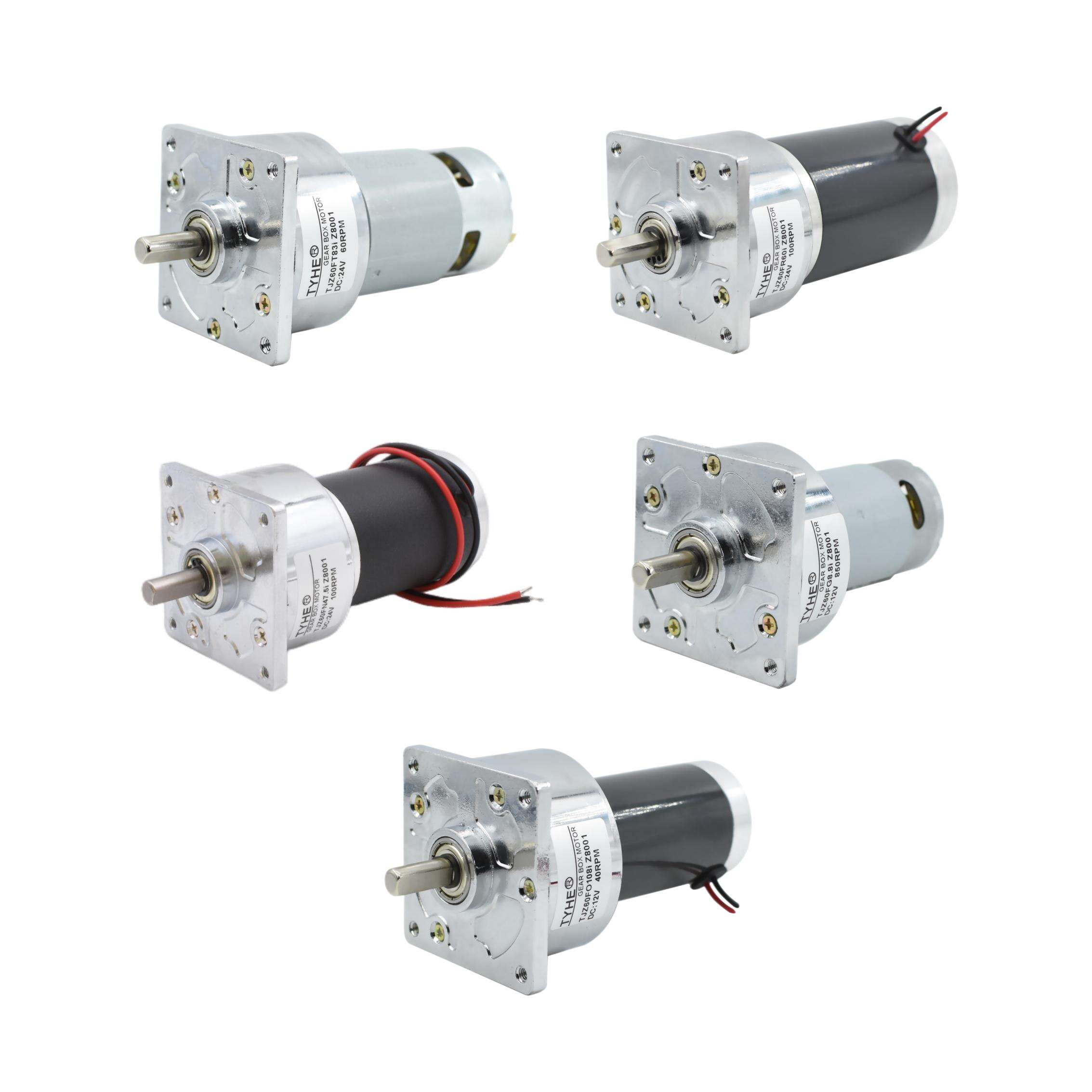
Understanding the fundamental principles behind electric motor technology is essential for engineers, technicians, and anyone working with electrical systems. The brush dc motor represents one of the most foundational and widely used motor designs in industrial applications, offering simplicity, reliability, and precise control characteristics. These motors have powered countless devices from small appliances to large industrial machinery, making them an indispensable component in modern engineering. Their straightforward construction and predictable performance characteristics have made them the go-to choice for applications requiring variable speed control and high starting torque.
Fundamental Components and Construction
Stator Assembly and Magnetic Field Generation
The stator forms the stationary outer structure of a brush dc motor and plays a crucial role in establishing the magnetic field necessary for motor operation. In permanent magnet brush dc motors, the stator consists of permanent magnets arranged to create a uniform magnetic field across the air gap. These magnets are typically made from materials like ferrite, neodymium, or samarium cobalt, each offering different magnetic strength and temperature characteristics. The magnetic field strength and uniformity directly impact the motor's torque production and efficiency.
For wound field brush dc motors, the stator contains electromagnets created by copper windings wrapped around steel pole pieces. These field windings can be connected in series, parallel, or as a separate excitation circuit, each configuration offering distinct performance characteristics. The steel pole pieces concentrate and direct the magnetic flux, ensuring optimal interaction with the rotor assembly. The air gap between stator and rotor is carefully designed to minimize magnetic reluctance while preventing mechanical contact during operation.
Rotor Design and Armature Windings
The rotor, also called the armature, consists of a laminated steel core with copper conductors embedded in slots around its circumference. These laminations reduce eddy current losses that would otherwise generate heat and reduce efficiency. The armature windings are precisely arranged in a specific pattern to ensure smooth torque production and minimize torque ripple. The number of conductors, their arrangement, and the commutator design all work together to optimize motor performance for specific applications.
Modern brush dc motor rotors incorporate advanced materials and manufacturing techniques to improve performance and durability. High-grade copper ensures low resistance losses, while precision balancing reduces vibration and extends bearing life. The rotor's moment of inertia affects the motor's acceleration characteristics, making it an important consideration for applications requiring rapid speed changes or precise positioning control.
Operating Principles and Electromagnetic Theory
Electromagnetic Force Generation
The operation of a brush dc motor relies on the fundamental principle that a current-carrying conductor in a magnetic field experiences a force perpendicular to both the current direction and magnetic field lines. This force, described by Fleming's left-hand rule, creates the rotational motion that drives the motor shaft. The magnitude of this force depends on the current strength, magnetic field intensity, and the length of conductor within the magnetic field.
When direct current flows through the armature conductors positioned in the stator's magnetic field, each conductor experiences a force that collectively creates torque around the rotor's axis. The direction of rotation depends on the current direction and magnetic field polarity, allowing for easy reversal by changing either the armature current or field current direction. This electromagnetic interaction converts electrical energy into mechanical energy with remarkable efficiency when properly designed and maintained.
Commutation Process and Current Switching
The commutation process is perhaps the most critical aspect of brush dc motor operation, enabling continuous rotation by systematically switching current direction in the armature conductors. As the rotor turns, carbon brushes maintain electrical contact with copper segments on the commutator, which is essentially a mechanical switch that reverses current flow in conductors as they move between magnetic poles. This switching must occur at precisely the right moment to maintain smooth torque production.
During commutation, the current in a conductor must change direction as it moves from one magnetic pole to another. This current reversal creates electromagnetic effects that can cause sparking, voltage spikes, and reduced brush life if not properly managed. Advanced brush dc motor designs incorporate interpoles or compensating windings to neutralize these harmful effects, ensuring reliable operation even under demanding conditions. The quality of commutation directly affects motor efficiency, electromagnetic interference, and overall reliability.
Performance Characteristics and Control Methods
Torque and Speed Relationships
The torque production in brush dc motors follows predictable mathematical relationships that make them ideal for applications requiring precise control. Motor torque is directly proportional to armature current, allowing for excellent torque control through current regulation. The speed-torque characteristic typically shows decreasing speed with increasing load, providing natural load regulation that many applications find beneficial. This inherent speed regulation helps maintain stable operation under varying load conditions.
Speed control in brush dc motors can be achieved through various methods, including armature voltage control, field weakening, and pulse width modulation. Armature voltage control provides smooth speed variation from zero to base speed while maintaining full torque capability. Field weakening allows operation above base speed by reducing the magnetic field strength, though this reduces available torque. Modern electronic controllers often combine these methods to achieve optimal performance across the entire operating range.
Efficiency Considerations and Power Losses
Understanding the various loss mechanisms in brush dc motors is essential for optimizing efficiency and predicting thermal behavior. Copper losses in both armature and field windings represent resistive heating that reduces efficiency and generates heat that must be dissipated. Iron losses in the magnetic circuit include hysteresis and eddy current losses that increase with frequency and magnetic flux density. Mechanical losses from bearings and brush friction, while typically small, become significant in high-speed applications.
Brush and commutator losses represent a unique aspect of brush dc motor efficiency, as the sliding contact creates both electrical resistance and mechanical friction. The brush voltage drop, typically 1-3 volts total, represents a relatively constant loss that becomes more significant in low-voltage applications. Proper brush selection, commutator maintenance, and operating environment control significantly impact these losses and overall motor reliability. Advanced brush materials and spring designs help minimize these losses while extending operational life.
Applications and Selection Criteria
Industrial and Commercial Applications
Brush dc motors find extensive use in applications where simple speed control, high starting torque, or precise positioning is required. Industrial applications include conveyor systems, packaging machinery, printing equipment, and material handling systems where variable speed operation is essential. The ability to provide high torque at low speeds makes brush dc motors particularly suitable for direct-drive applications that would otherwise require gear reduction.
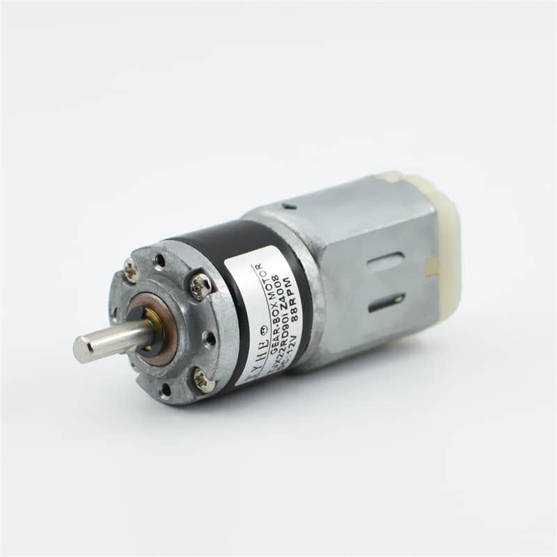
In automotive applications, brush dc motors power windshield wipers, power windows, seat adjusters, and cooling fans where their compact size and reliable operation are valued. Small brush dc motors are ubiquitous in consumer electronics, powering everything from computer fans to electric toothbrushes. Their ability to operate directly from battery power without complex electronic controllers makes them ideal for portable applications where simplicity and cost-effectiveness are priorities.
Selection Parameters and Design Considerations
Selecting the appropriate brush dc motor requires careful consideration of multiple performance parameters including torque requirements, speed range, duty cycle, and environmental conditions. The continuous torque rating must accommodate the application's steady-state requirements while the peak torque rating must handle starting and acceleration demands. Speed requirements determine whether standard motor designs are sufficient or if special high-speed construction is necessary.
Environmental factors significantly influence brush dc motor selection and design. Temperature extremes affect brush life, magnetic properties, and winding insulation, requiring careful material selection and thermal management. Humidity, contamination, and vibration levels all impact reliability and maintenance requirements. Applications in hazardous environments may require special enclosures, explosion-proof construction, or alternative motor technologies. The expected maintenance intervals and accessibility for service also influence the selection process.
Maintenance and Troubleshooting
Preventive Maintenance Procedures
Regular maintenance is crucial for ensuring reliable operation and extending the service life of brush dc motors. The commutator and brush assembly require the most attention, as they are subject to wear and contamination that can affect performance. Periodic inspection should check for even brush wear, proper spring tension, and commutator surface condition. Brush replacement should occur before excessive wear creates poor contact or allows brush holders to contact the commutator surface.
Bearing maintenance involves regular lubrication according to manufacturer specifications and monitoring for excessive noise, vibration, or temperature rise that might indicate impending failure. The motor housing should be kept clean and free from debris that could block ventilation openings or create contamination paths. Electrical connections require periodic inspection for tightness, corrosion, or overheating signs that could lead to performance degradation or failure.
Common Problems and Diagnostic Techniques
Excessive sparking at the brushes indicates problems with commutation that can result from worn brushes, contaminated commutator surface, or improper brush adjustment. High resistance connections, overloading, or incorrect voltage can also cause increased sparking and reduced motor life. Diagnostic procedures should include visual inspection, electrical measurements, and vibration analysis to identify developing problems before they cause failures.
Motor overheating can result from overloading, blocked ventilation, bearing problems, or electrical faults that increase losses. Temperature monitoring during operation helps identify abnormal conditions, while current measurements can reveal mechanical overloading or electrical problems. Unusual noise or vibration often indicates mechanical problems such as bearing wear, shaft misalignment, or unbalanced rotors that require immediate attention to prevent further damage.
FAQ
What is the main difference between brush dc motors and brushless dc motors
The primary difference lies in the commutation method used to switch current in the motor windings. Brush dc motors use mechanical commutation with carbon brushes and a segmented commutator, while brushless dc motors use electronic switching with semiconductor devices controlled by position sensors. This fundamental difference affects maintenance requirements, efficiency, electromagnetic interference, and control complexity, with each type offering distinct advantages for specific applications.
How long do brushes typically last in a brush dc motor
Brush life varies significantly depending on operating conditions, motor design, and application requirements, typically ranging from hundreds to thousands of hours of operation. Factors affecting brush life include current density, commutator surface condition, operating temperature, humidity, and vibration levels. Motors operating at high currents, elevated temperatures, or in contaminated environments will experience shorter brush life, while motors in clean, controlled environments with moderate loading can achieve much longer brush life.
Can brush dc motors be speed controlled without losing torque
Brush dc motors can maintain full torque capability throughout their speed control range when using armature voltage control methods. By varying the applied voltage while maintaining full field strength, the motor can operate from zero speed to base speed with constant torque available. Above base speed, field weakening techniques can extend the speed range, but available torque decreases proportionally with the reduction in magnetic field strength.
What causes brush dc motors to generate electromagnetic interference
Electromagnetic interference in brush dc motors primarily results from the commutation process, where rapid current switching creates voltage spikes and high-frequency electrical noise. The mechanical contact between brushes and commutator segments generates arcing that produces broadband electromagnetic emissions. Poor commutation due to worn brushes, contaminated commutator surfaces, or improper timing exacerbates these effects, making proper maintenance and design critical for minimizing electromagnetic interference in sensitive applications.
